
Spinning a Web
In March of 2023 I was invited to a Willow Springs track event by none other than Bob Pham. I decided to make a little trip out of it, hang out with my good friends Max (yes, BAR 2AR (and now BAR 2GR) Max) and Omar, and do a few LA things, such as Universal Studios.
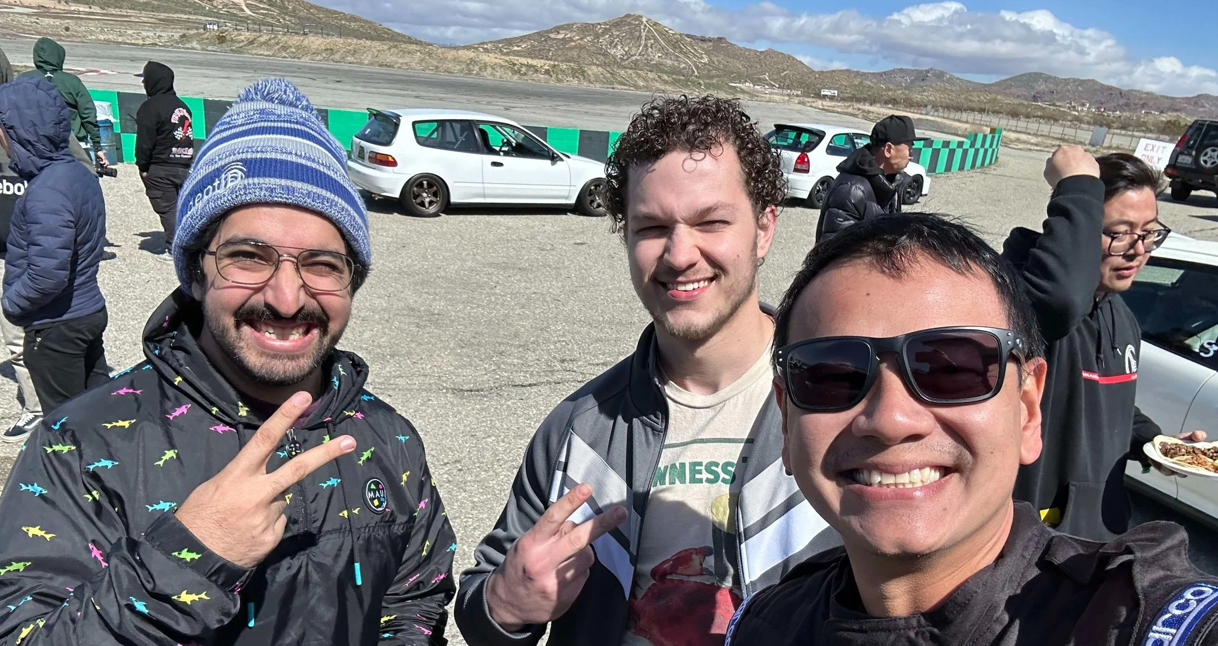
Proof that Bob and I are homies
Bob was kind enough to let me drive ANY of his cars that weren’t currently occupied. I’d driven a couple SW20s on track, including my own, but you know what I hadn’t driven?
Arachnis Deathicus
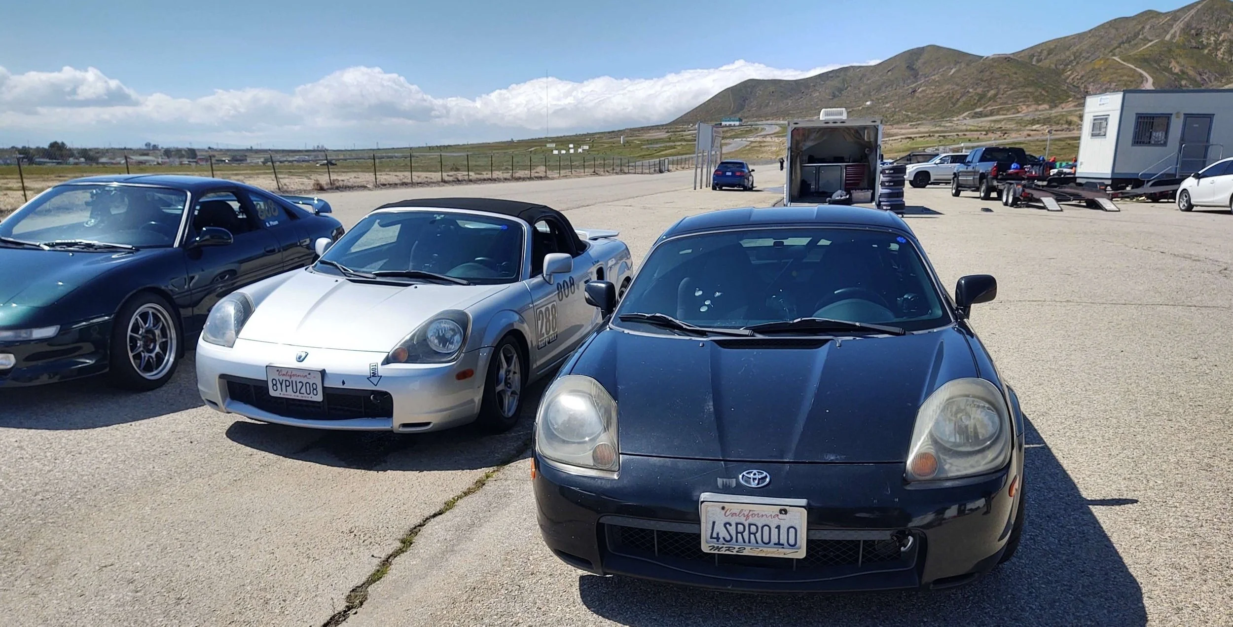
I had never driven a Spyder, on or off track. Bob had two there, and I decided to drive both of them. These were very similar cars, both had unmodified 1ZZs. The primary difference between the two was the black car had a hardtop with a 5 speed on lowering springs, and the grey car had a softtop with a 6 speed on 808 coilovers. It was awesome to see the difference in suspension and gearing back to back. My best lap was less than two seconds off the car’s track record. Needless to say, I was impressed with the car. It was then I decided I needed one.
Fast forward a few months, and after a bit of searching, I found something to scratch the itch.
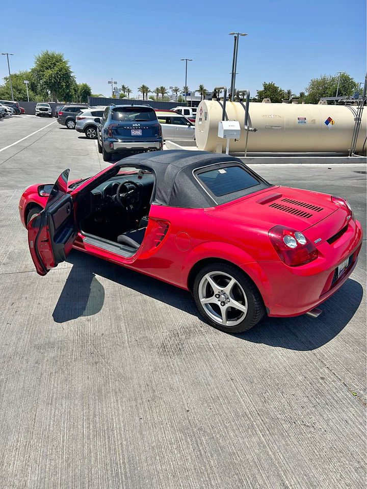
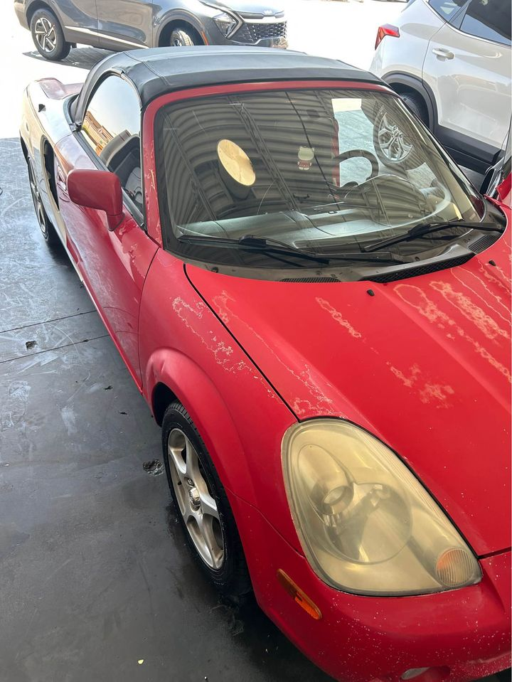
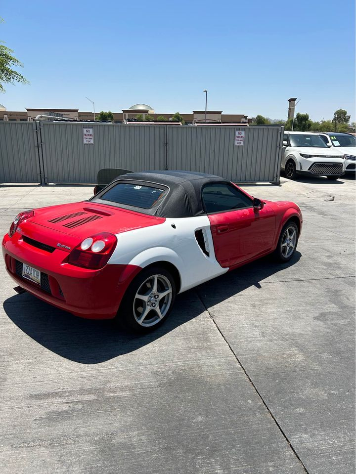
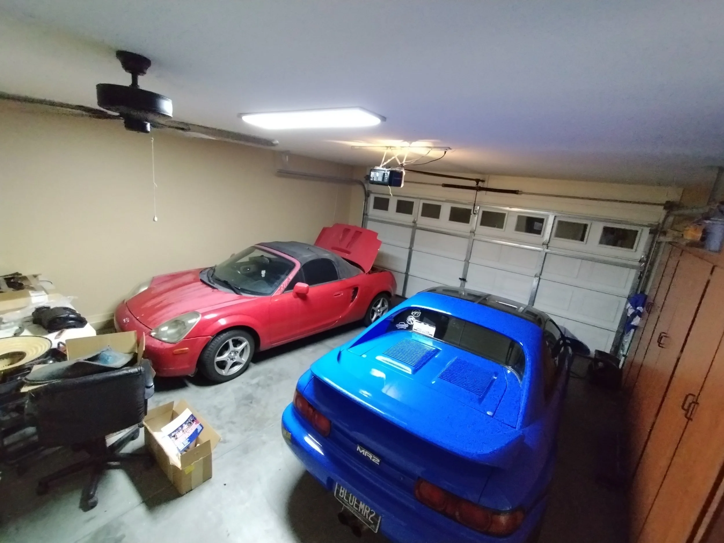
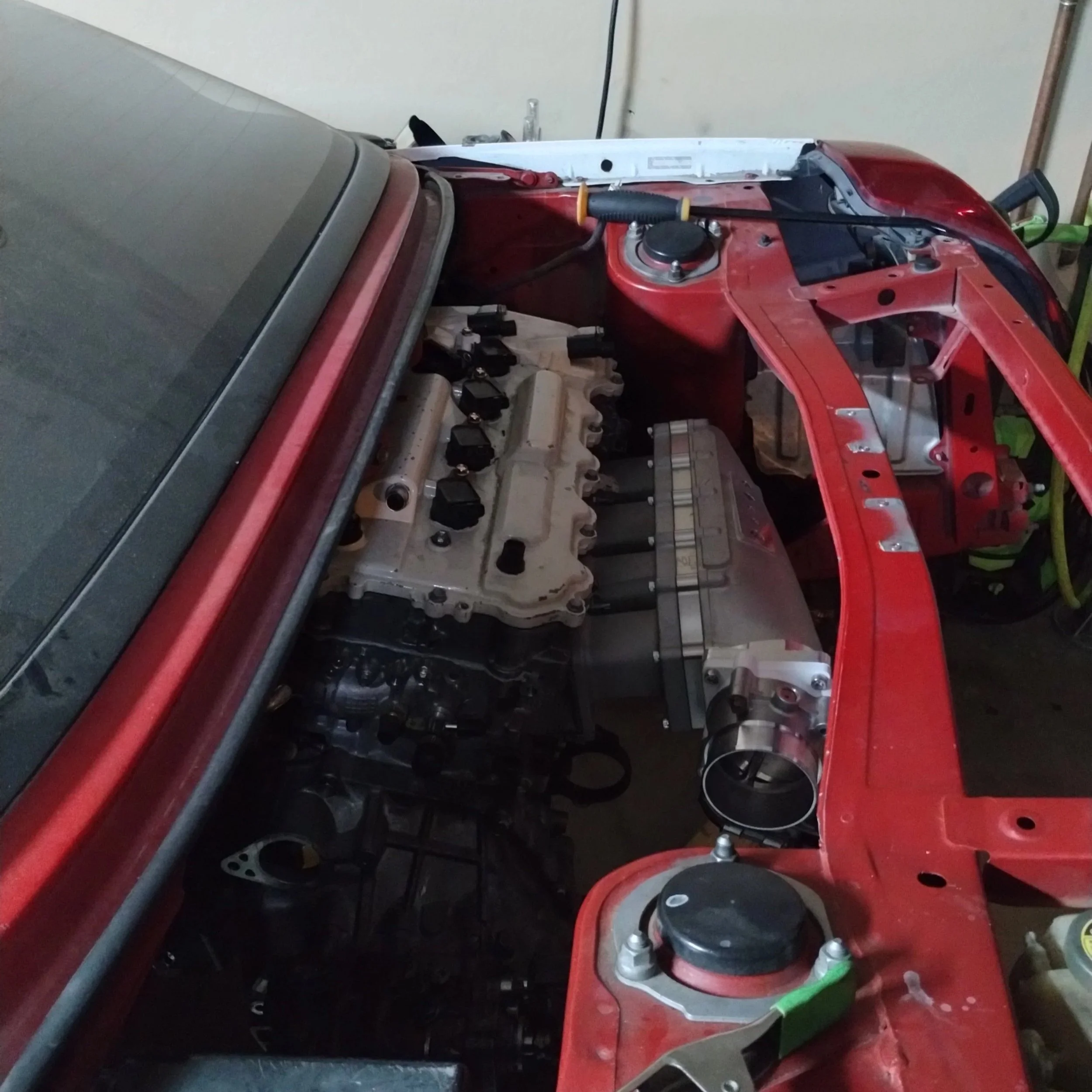
Here’s my new Spyder! There were a few ups and a few downs. It’s a facelift car, mildly beat up. It had a new but aftermarket softtop, and one mismatched quarter with no damage underneath. The chassis was in really good shape, and all the suspension and brakes were in good order. Oh yeah, and it’s an SMT with a BLOWN 1ZZ. “Blown” is an understatement here. It burned more oil than anything I’ve ever seen, sounded like it was falling apart by the minute, and would completely stall when warm and in gear. It was probably running on two cylinders. At least the SMT worked pretty well, but it grinded third a tiny bit. That’s pretty much par for the course on Toyota transmissions. It would be an easy fix for me, but it’s not something I’m really worried about at the moment.
The one thing I felt about Bob’s Spyder was that, while it was great and drove well, it really is a little lacking in power for larger road courses. I know that’s an easy logical fallacy to fall into, but given how close I was to the car’s track record, I feel confident in my assessment. So of course, it’s time for a 2AR. Or a 1AR. Yeah, a 1AR. I’ve driven my 1AR RAV4 around for some time, and it’s SO nice. It really is a fantastic engine. I hope more people open up to moving to the AR platform as time goes on. As more people do these swaps I think it’s only a matter of time.
It was surprisingly easy for me to source the manual swap parts. Clutch and brake pedals, shifter, and cables, all within a week of owning the car. Coming from SW20-landia, that seemed absolutely insane to me. I expected a lot more difficulty here.
One thing I’d like to do a little differently from the “typical” 2AR Spyder is the transmission. Marc designed his kit around the EB60 because of its small size. It fits in the Spyder engine bay without cutting or notching anything. Instead, I’d like to use an E350 for my swap. I have more spare parts for it, I’m more familiar with the E platform, and there are more gearing options available. I could notch a subframe if necessary. I thought the shift linkage would be pretty easy. The C56 from a manual Spyder has a shift setup very similar to the FWD E series boxes. Similar enough that sometimes people with high-power 2ZZs use an adapter plate and an E series.
Monkeywrench Racing even sells a kit to mate an E153 to a 2ZZ in a Spyder. This kit is around $4000 and includes the shift linkage. Unfortunately, this kit will not work with this swap, even if I were using an E153. MWR keeps the 2ZZ starter, which is engine block-side, while any combination of 2AR and E series will result in a transmission-side starter. The starter lives roughly where one of their shift brackets sits. I had to come up with something on my own.
I went and got a transmission from a 2007 tC at my nearest junkyard.
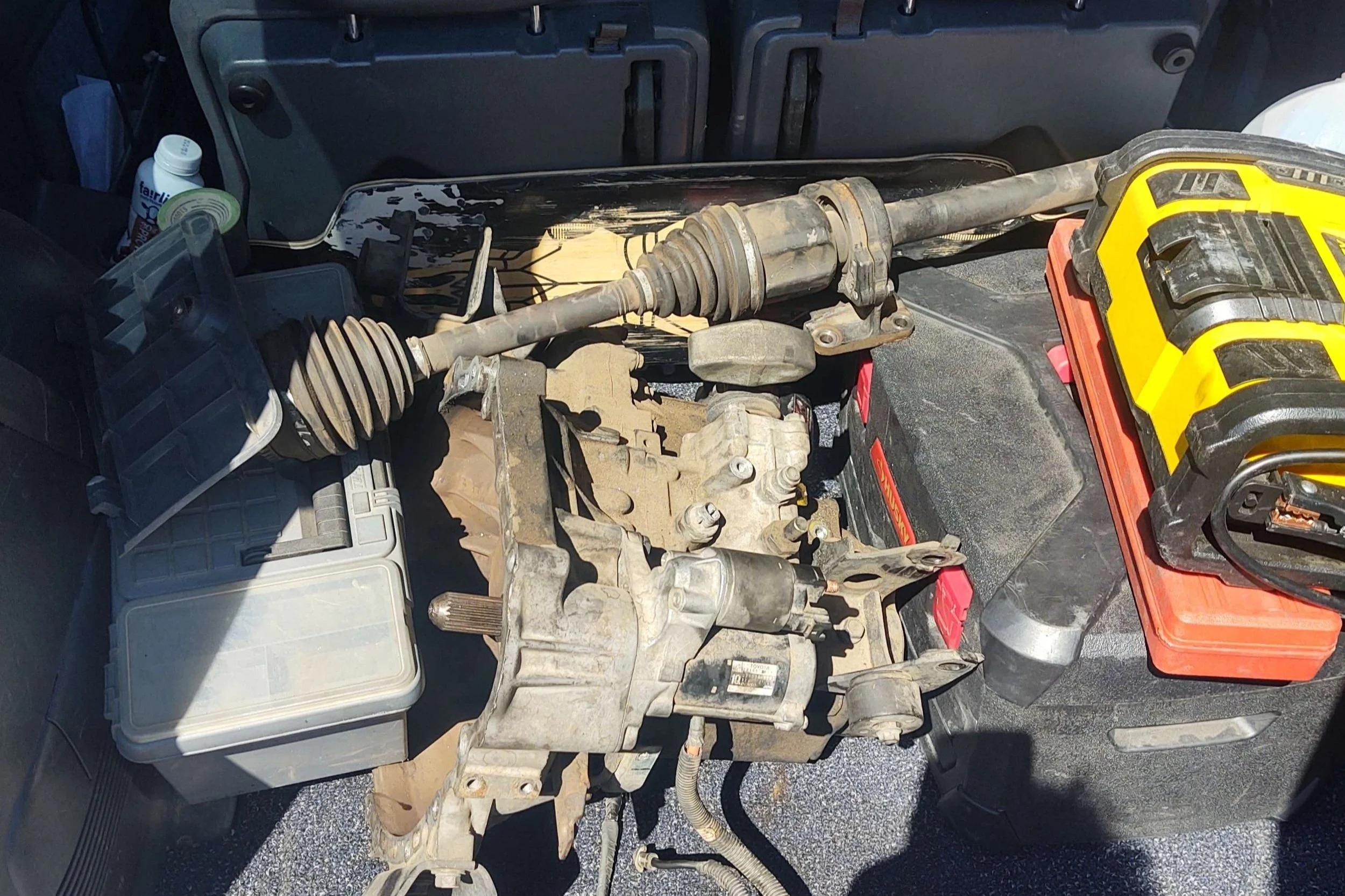
Luckily, now that I had my RAV4 driving again (peak automobile), I could go grab that gearbox. I can pull one out in about an hour or so. I don’t even use a jack or anything, I let the motor fall a bit and sit against the firewall, which allows me enough tilt to unbolt the transmission to slide it off, dropping to the ground. These don’t weigh very much compared to something like an E153. Took it home, gave it a nice bath, and proceeded to the next step.
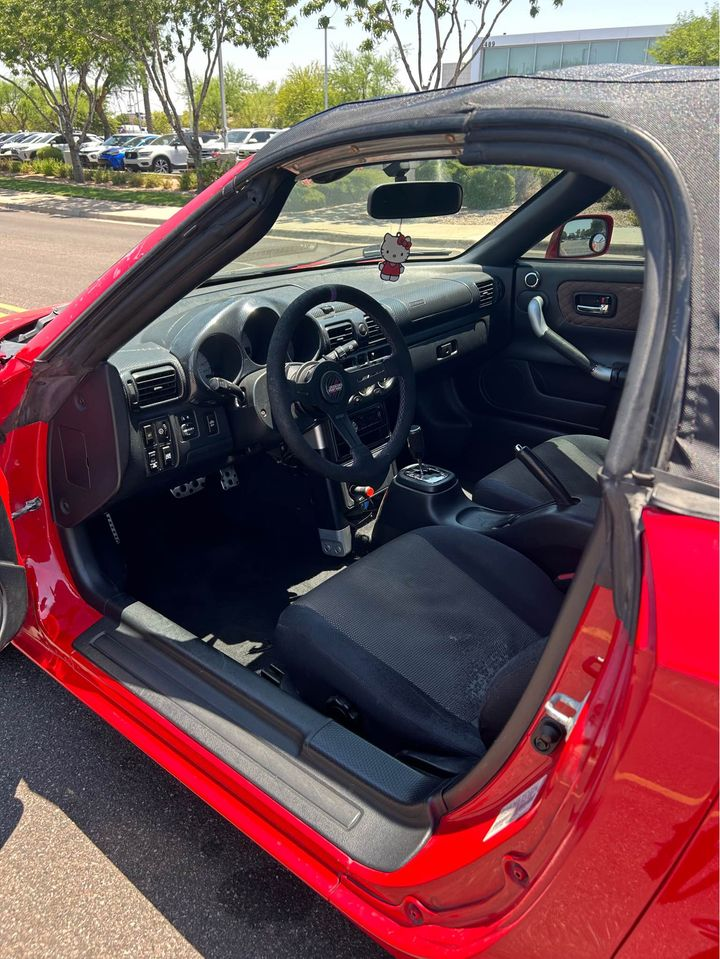
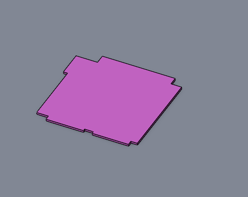
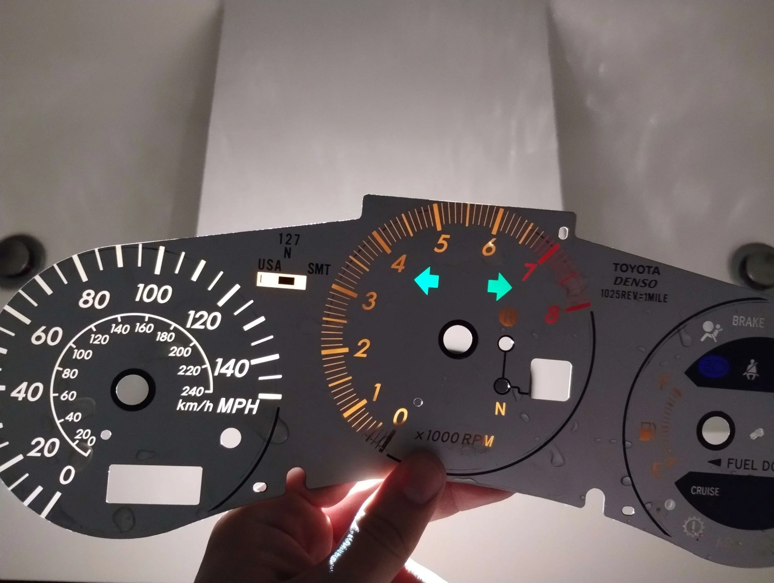
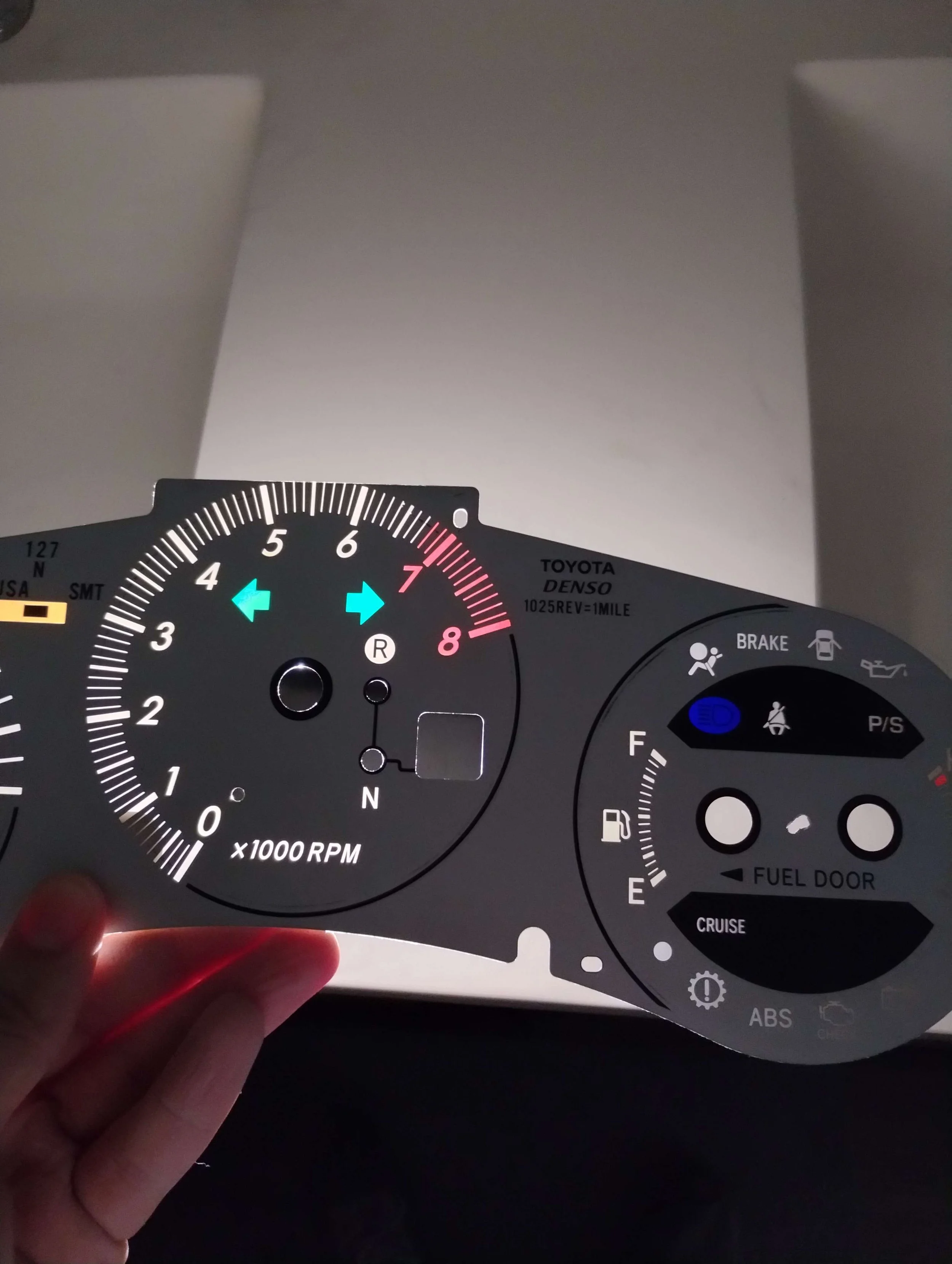
Now, of course, I had to find the most important part of a manual swap on an MR2 Spyder: the gauge cluster. The only difference between a manual and SMT gauge cluster is that the SMT has a seven-segment display that shows gear selection. Rather than source an actual manual gauge cluster, I decided to just cover everything up with a custom gauge face. I had never built a car with a lot of aesthetic modifications, so I figured this was the one.
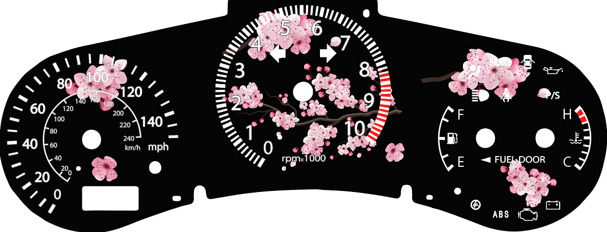
It’s a little silly but I thought it fit the car. I also took this opportunity to increase the tach from 8k to 10k rpm. No, I don’t plan to go to 10k rpm, and the gauge cluster will actually stop displaying anything after 8k, But 10k is cooler. However, there’s a part of me that’s considering reverse-engineering the gear display to display the manual transmission gear selection. Because of this, I pushed off my cherry blossom cluster. I saw two routes do do this. Option one is to add sensors. Option two is to do math. I could add a sensor on the gearstick, or to the actual shifter shaft on the transmission. These are difficult but not impossible. The math method works out pretty accurately, except at really low rpm. By using your speed and RPM, you can calculate which of the 5 gear ratios you’ve selected. The wider a gear spacing is, the more accurate this method is. This can be done natively on most standalone ECUs. However, I had a more pressing matter to solve on this cluster.
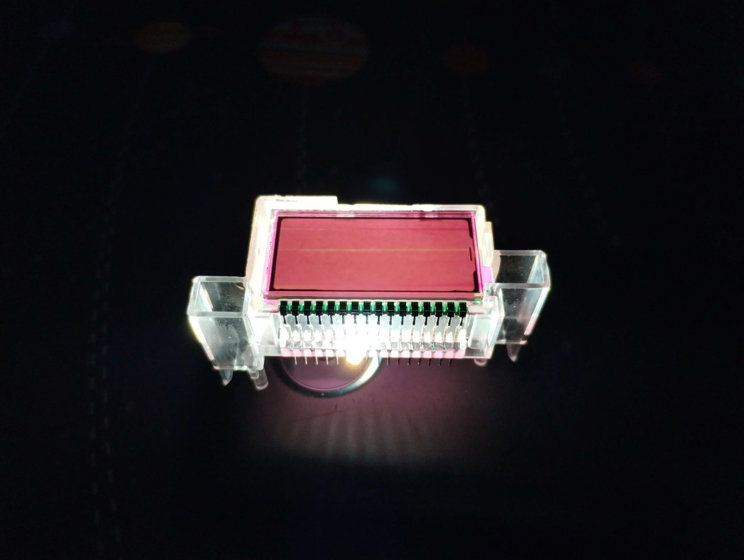
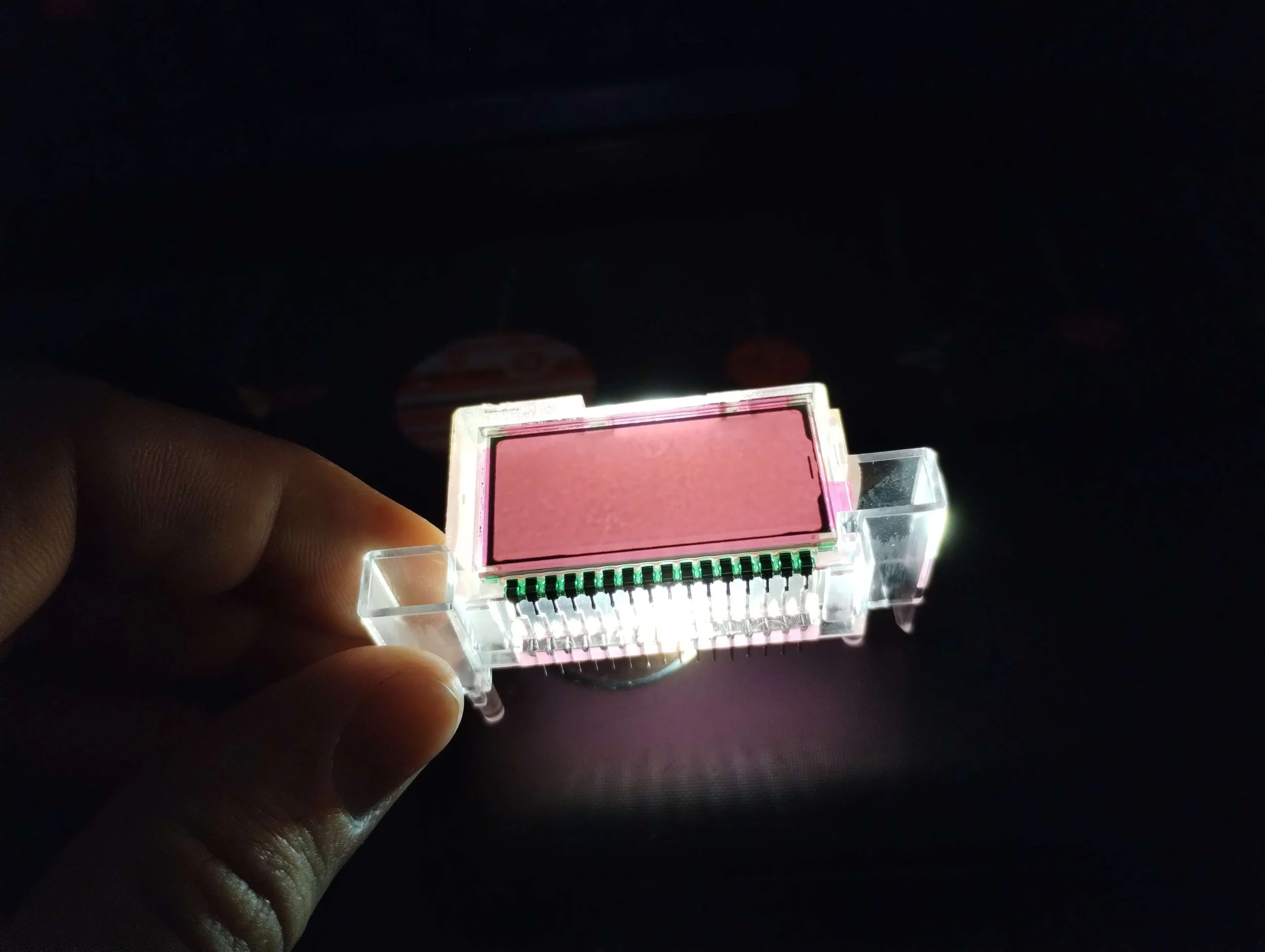
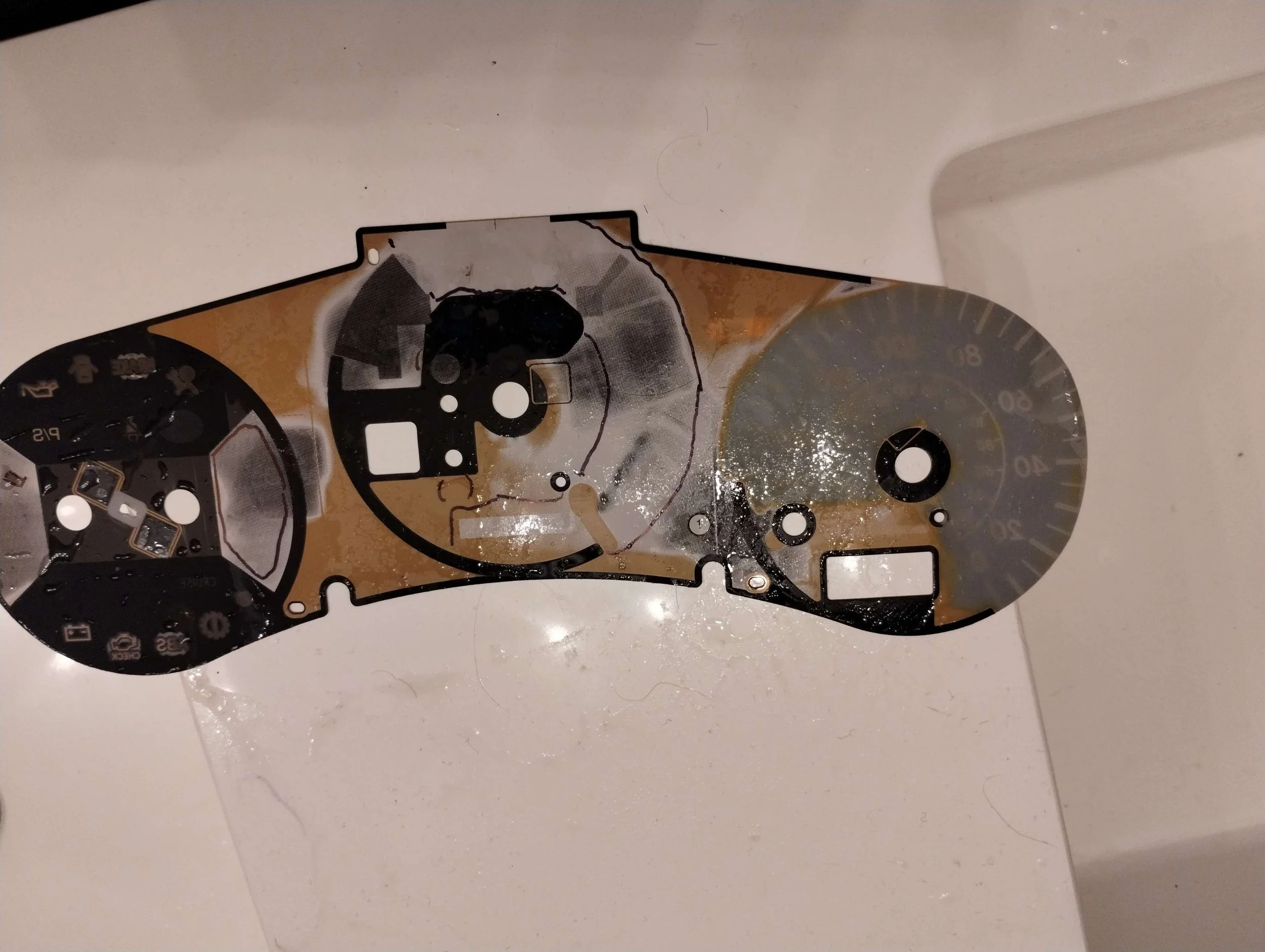
The display was orange.
This was detrimental to the pink aesthetic I’m going for. So I decided to take the whole cluster apart to see how difficult it would be to change the colors.
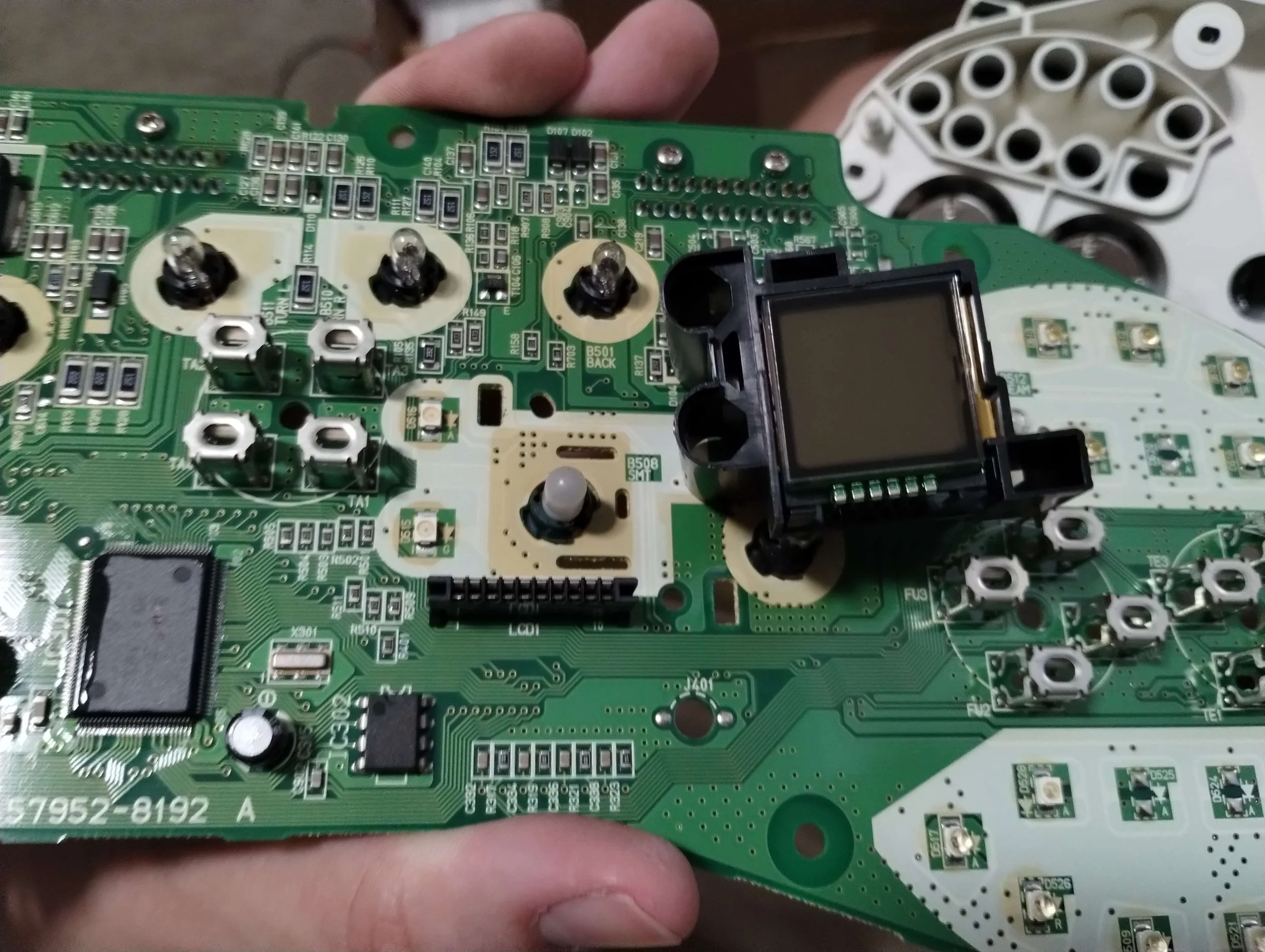
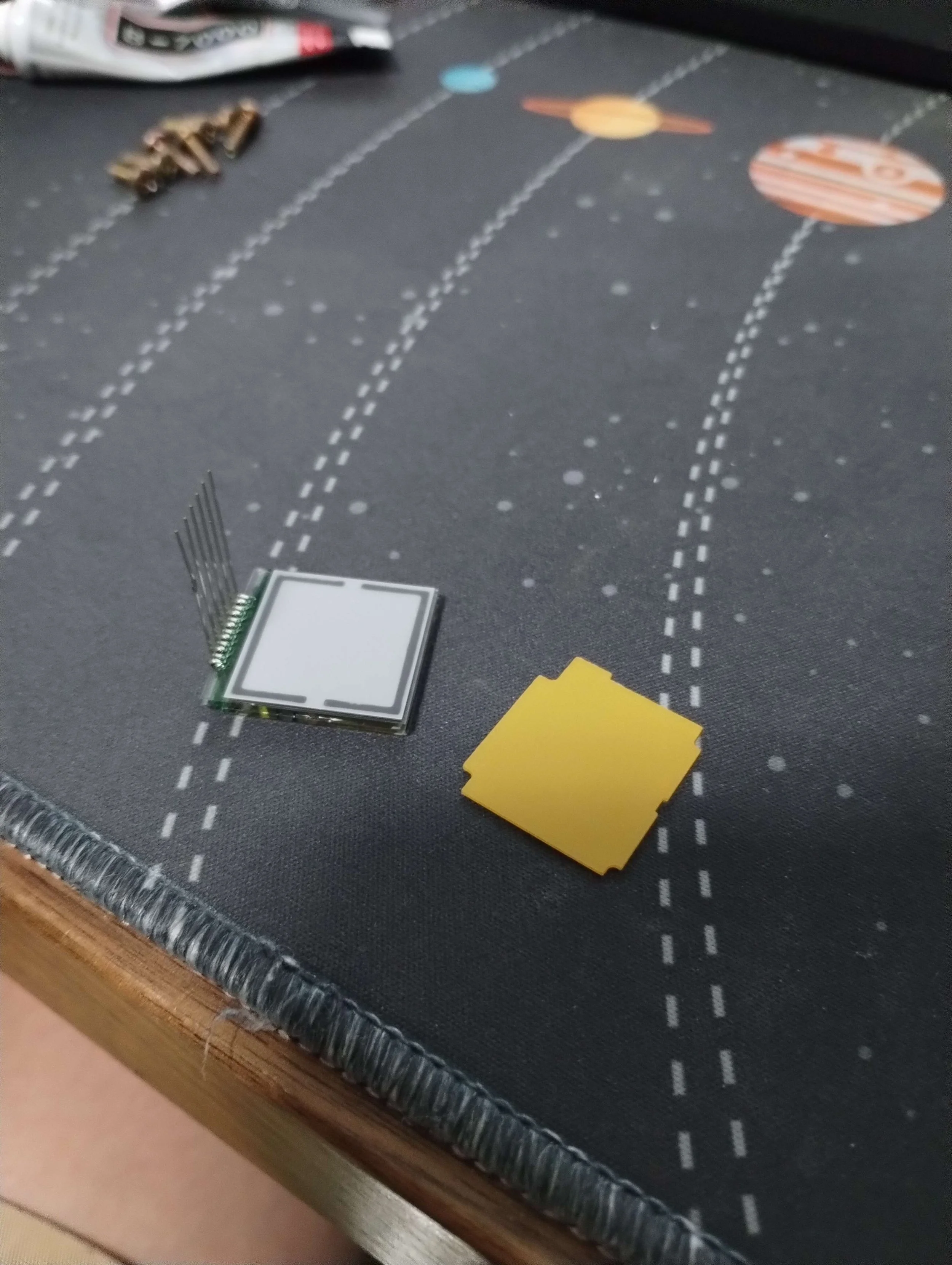
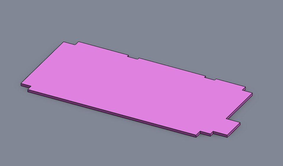
Oh, it just kinda pops out. I expected that there would be desoldering and/or removing epoxy. It seemed that I would just need to replace that orange plastic piece and probably the LED underneath it. Easy enough. The odometer display is assembled the same way, so I modeled both parts out, and I figured I could get these laser cut out of some translucent plastic.
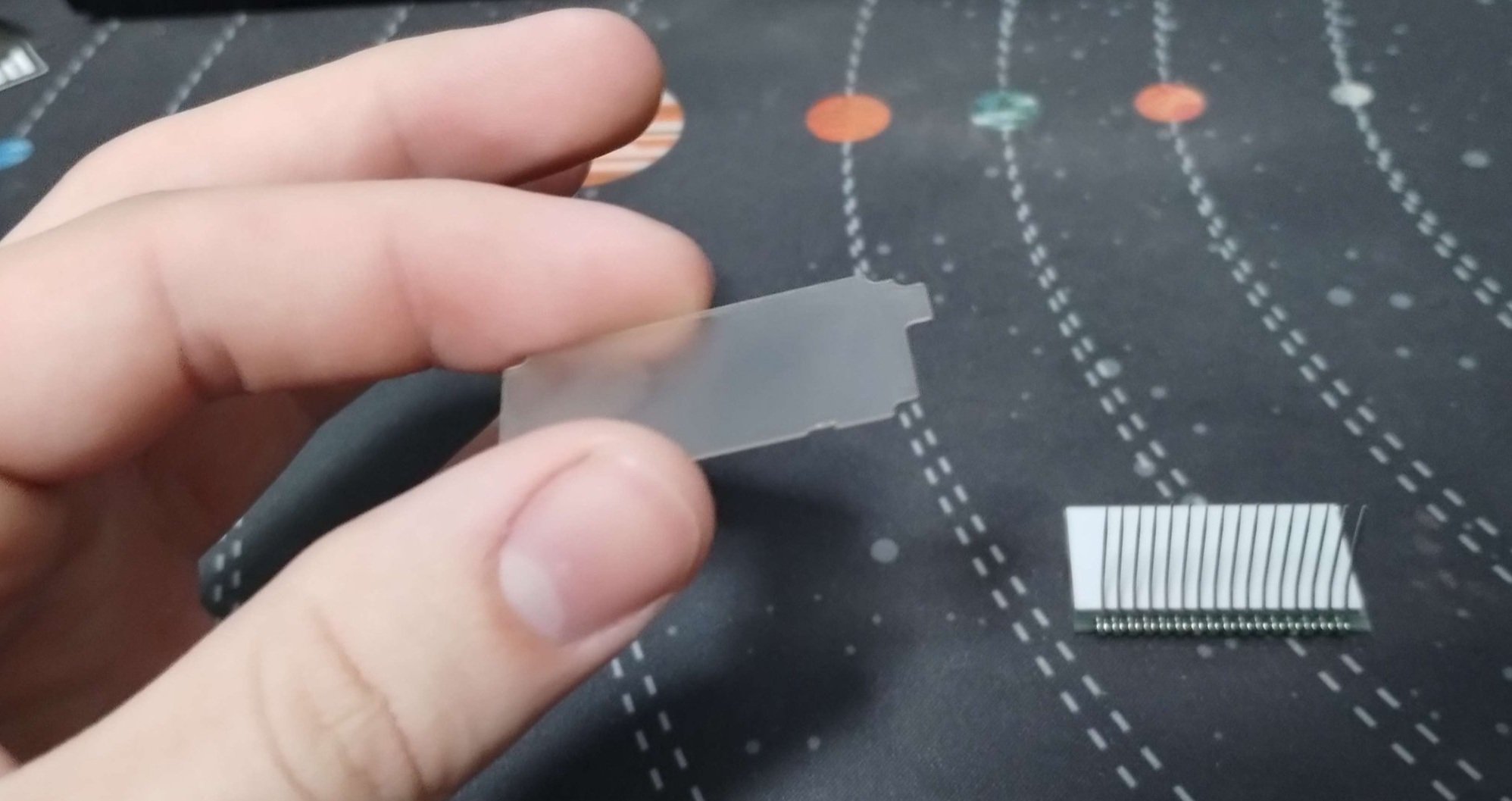
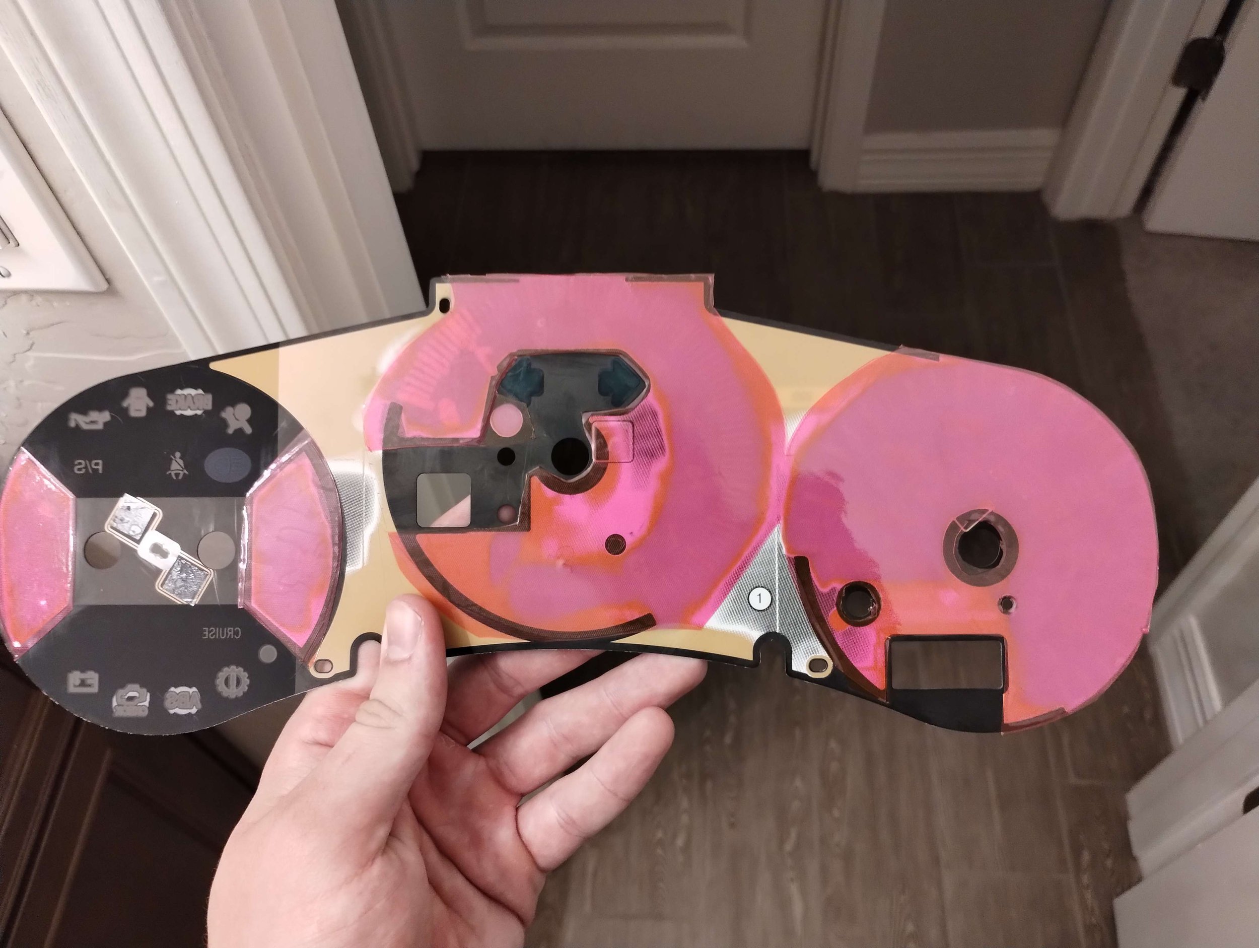
Immediately after modeling these parts, I realized that this was completely moot. The orange film is just a thin coating that is easily removed. I used a 1500 grit sandpaper, then headlight polish to remove the majority of the scratching. This took some trial and error, but there seemed to be a pretty wide margin for error. I made a few burn spots on the plastic, but I couldn’t quite pick these up on camera.
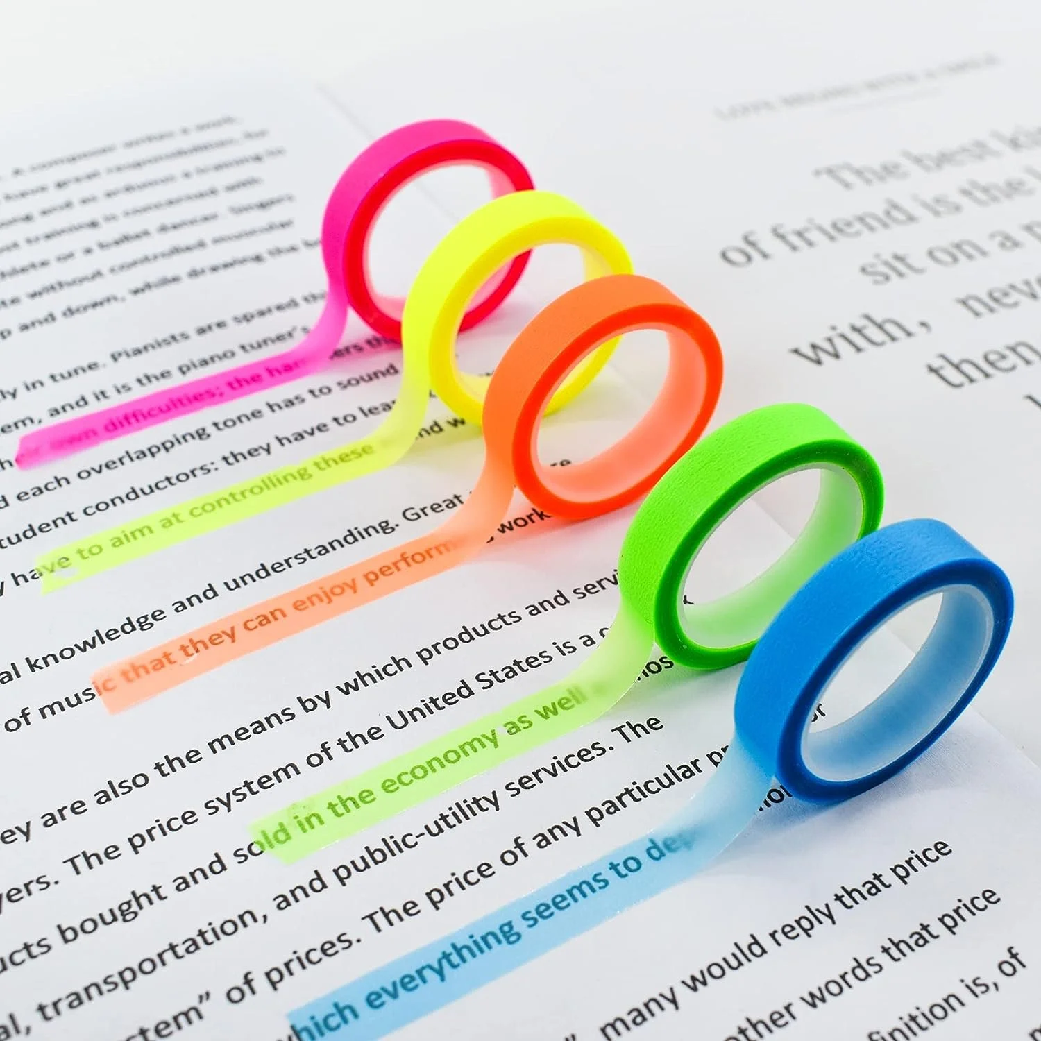
So, I could either leave these clear with colored LEDs, or try my hand at making them a different color. I could try to paint them or color them with some kind of marker. I didn’t think that would turn out very well. My first thought on this was to find some translucent pink tape. I bought some translucent “highlighter tape” which is available in pink. Rad. It’s pretty thin at only ~1cm wide, so I had to run several strips next to each other. This worked out really well besides the very obvious lines where I did not perfectly align the tape.
Oh well, fantastic proof of concept at the least. I struggled to find a wider tape in a similar price bracket. But then it hits me. Colored transparent film. Hmm. Window tint. That’s available in just about every color and finish. I realized I could buy that in individual pieces sold as “headlight tint”. I don’t know why someone would make their headlights pink, but others will say the same thing about my gauge cluster.
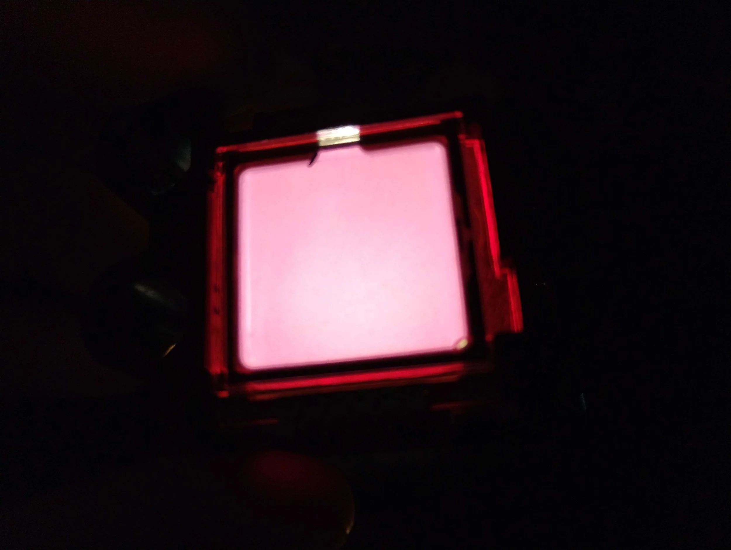
I was pretty happy with that. I went with two layers to enhance the pink. This exercise made me wonder if I can repeat the same process with the gauge faces…
I popped all of the needles off, removed the face plastic, and started to wet-sand the orange off, just like I did on the LCD backgrounds. Slowly but surely, I removed all the orange, then applied the pink film.
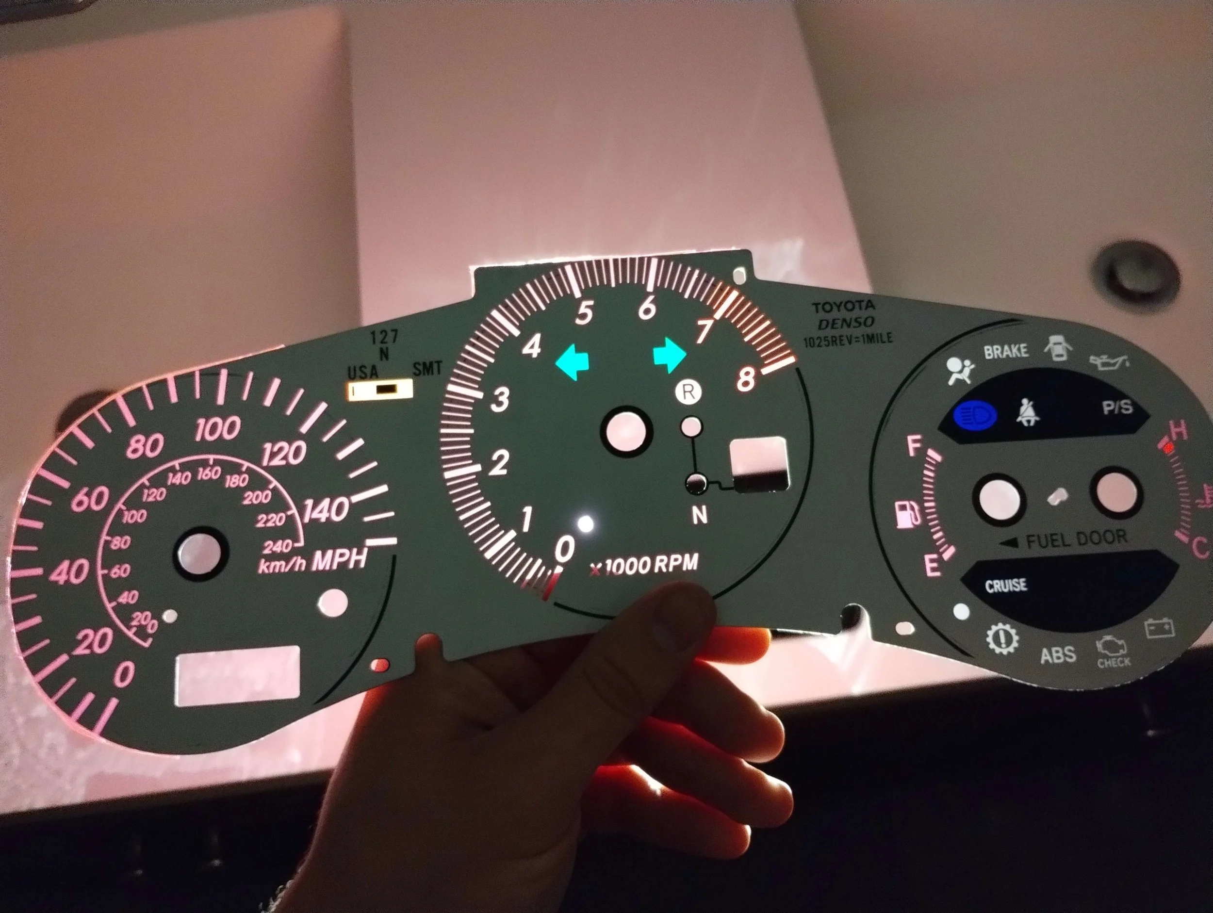
I was unreasonably excited about this. Using this same method, one could easily individually color each element on the cluster, along with the indicator lights. If anyone else copies this, just go slow, wet sand, clean your gauge face often, and constantly recheck your work. You don’t want to remove very much material.
Next it was time for the engine. I know 2ARs are always available so I was not at all worried about this. Not a priority, so I paused the build. That being said, one pretty much fell into my lap. None other than Max Sehic was selling the 2AR out of his California-legal swapped SW20. He wasn’t getting any bites, so I had him bring it out to me. Something uncertain about this build concept was if the output of an E series transmission would line up with any 2AR axle carrier bracket. Now that I had a 2AR and E350 sitting around, it was finally time to test.
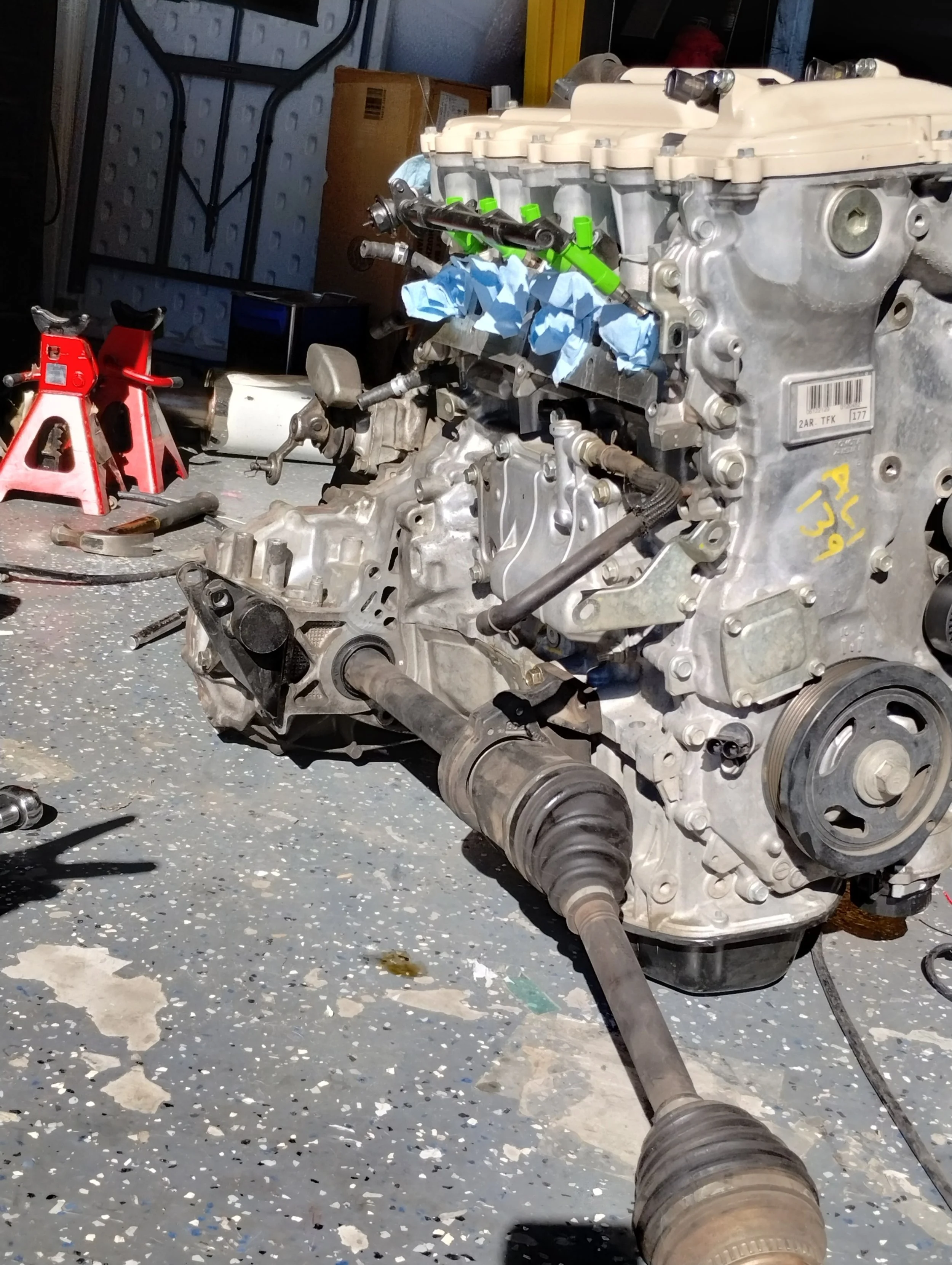
As it turns out, the 2AZ and 2AR share the same axle carrier bolt pattern. This axle and carrier are from a first gen Scion tC, and they align perfectly against a 2AR, perfectly spaced away from the transmission. The more I dug into it, the more it seemed like Toyota took what they learned from the 2AZ and 2GR to build the 2AR. So much in common with the 2AZ and so many improvements over the 2GR.
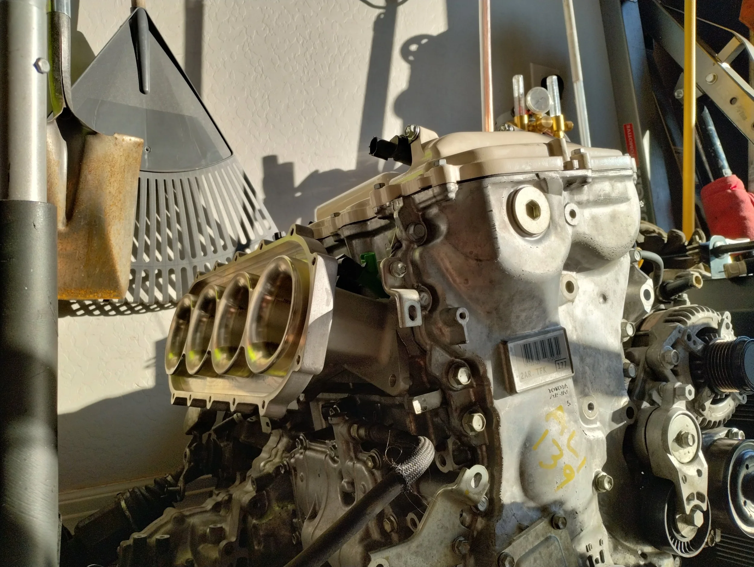

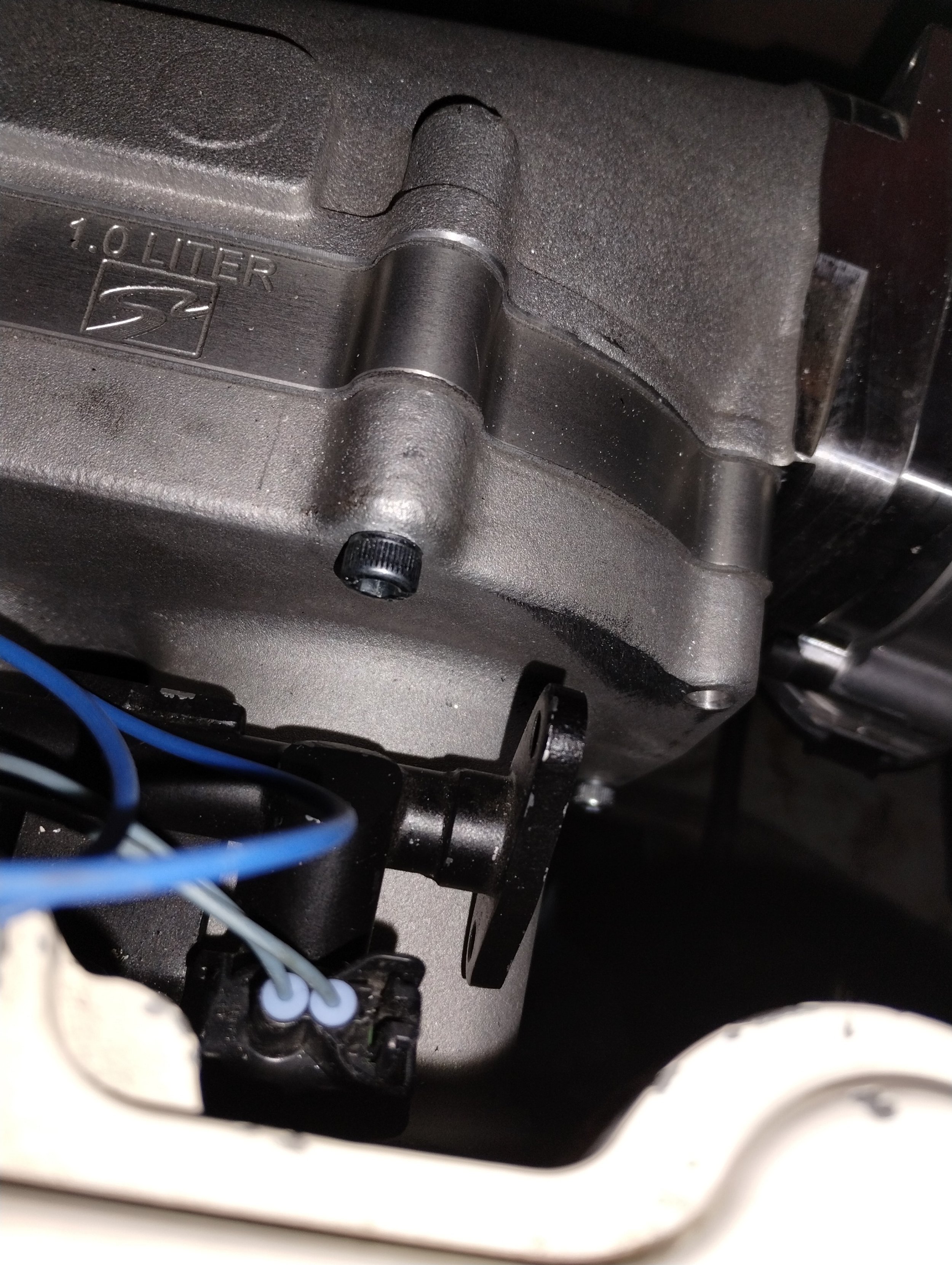
I grabbed a Frankenstein Motorworks intake with a Skunk2 plenum and 1L spacer. This thing is gorgeous, and has been proven to make 270 naturally aspirated horsepower with stock 2AR-FE internals with cams. Somewhat surprisingly, this whole combination weighs the same as a factory 2AR intake. In the future I’d love to make a plastic version of the Skunk2 plenum, ideally with the spacer built in. That’s called added lightness.
For a multitude of reasons my car sat in a storage unit on the other side of the city. I needed to get that car to my house. I don’t have a truck and don’t want to rent one. My RAV4 could probably tow it on a dolly, but that’s pushing the limit of what I’m comfortable with. So, I attempted to drive my Spyder home. My rod knocking, oil burning, barely running Spyder. Being across the city, the only way to get home was on the freeway.
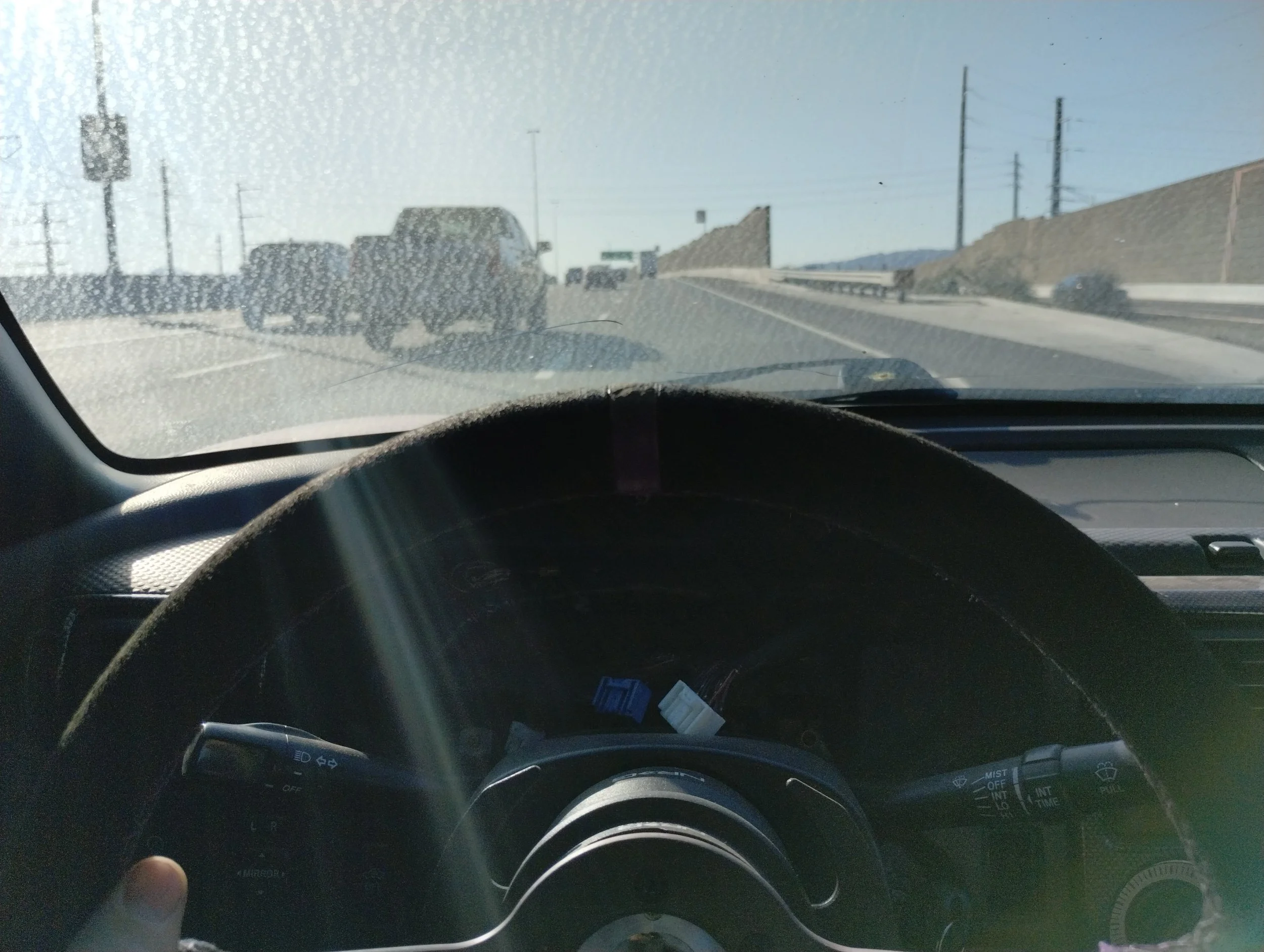
Somehow I managed to forget my gauge cluster at home. Flying totally blind here.
An unfortunate development, this car would not stay running. My foot had to be on the gas. This made driving especially difficult with the SMT. It would stall at every stop, so driving it consisted of starting it, letting it settle, FLOORING it until the engine picked up to around 2000 RPM, then drop it into gear and let the computer figure out the rest. Something else that sucked in this situation is that part of the AC system is handled by the gauge cluster. Forgetting mine meant I had no AC, in late summer in Arizona. This car probably would have died if I turned the AC on anyway. For some reason, the softtop frame was bound up, preventing me from putting the top down. That meant windows down only, for 40 miles.
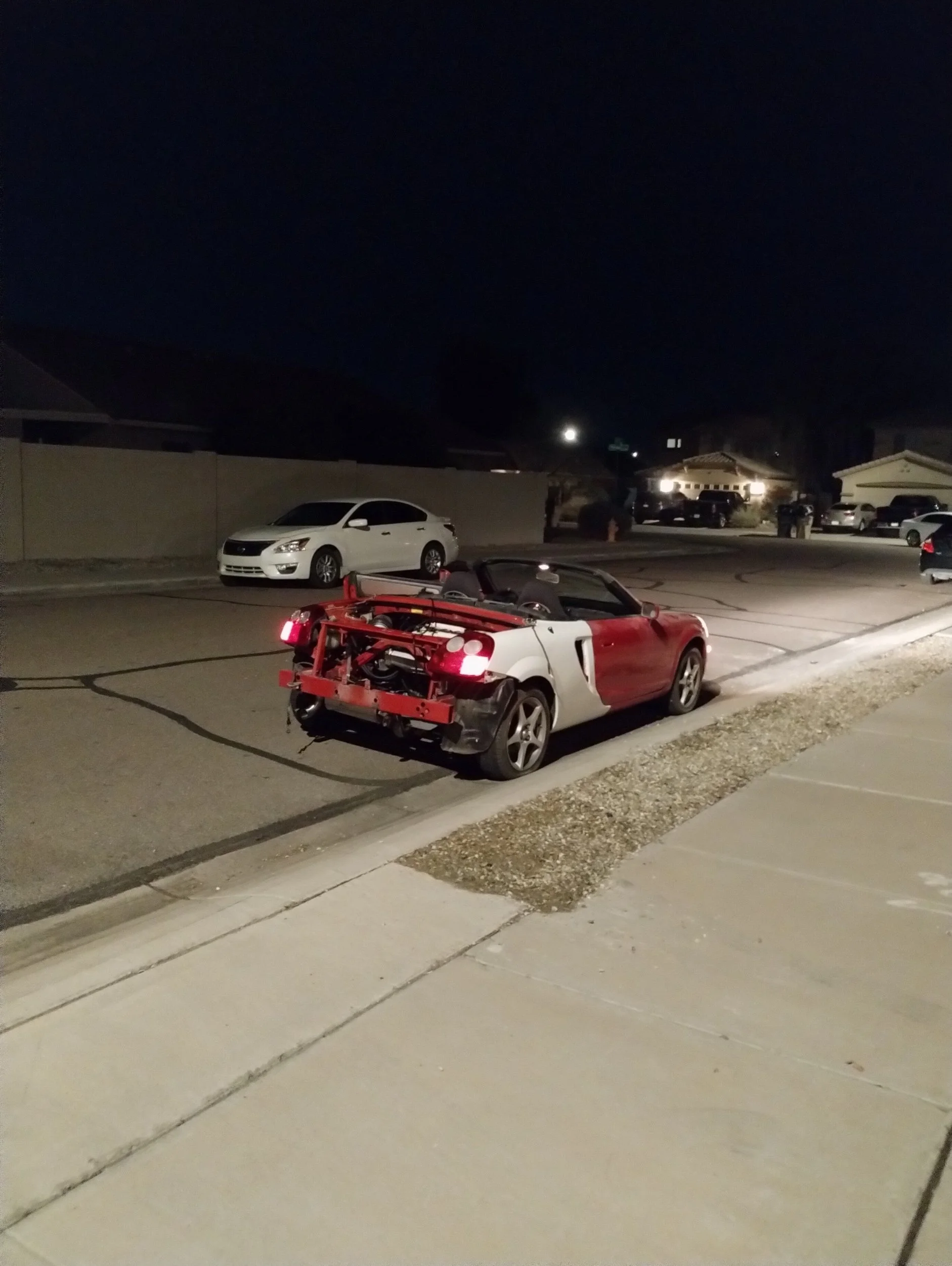
Surprisingly, I was able to keep up with freeway speeds, but I had to floor it the whole time. I could barely maintain ~70mph on flat roads. With a little napkin math, I can figure out the horsepower it was making. The MR2 Spyder has a drag coefficient of 0.353, frontal area of 22.3 square feet. That equals about 105lb of force at 70mph, or about 20hp. Add a little extra for math errors and rolling resistance, call it 40hp, with my foot to the floor. Neat. I got pretty far, about 23 of the 37 mile drive home. As I crested one final hill I felt the engine start to shake and knock louder and louder. Suddenly, I lost all power. Nothing. Dropping it in and out of gear didn’t do anything, not that I expected it would. Luckily, I got to exactly where I wanted to be, and I can flat tow it the rest of the way home. I got it to a parking lot to leave overnight, I could get a second driver in the morning.
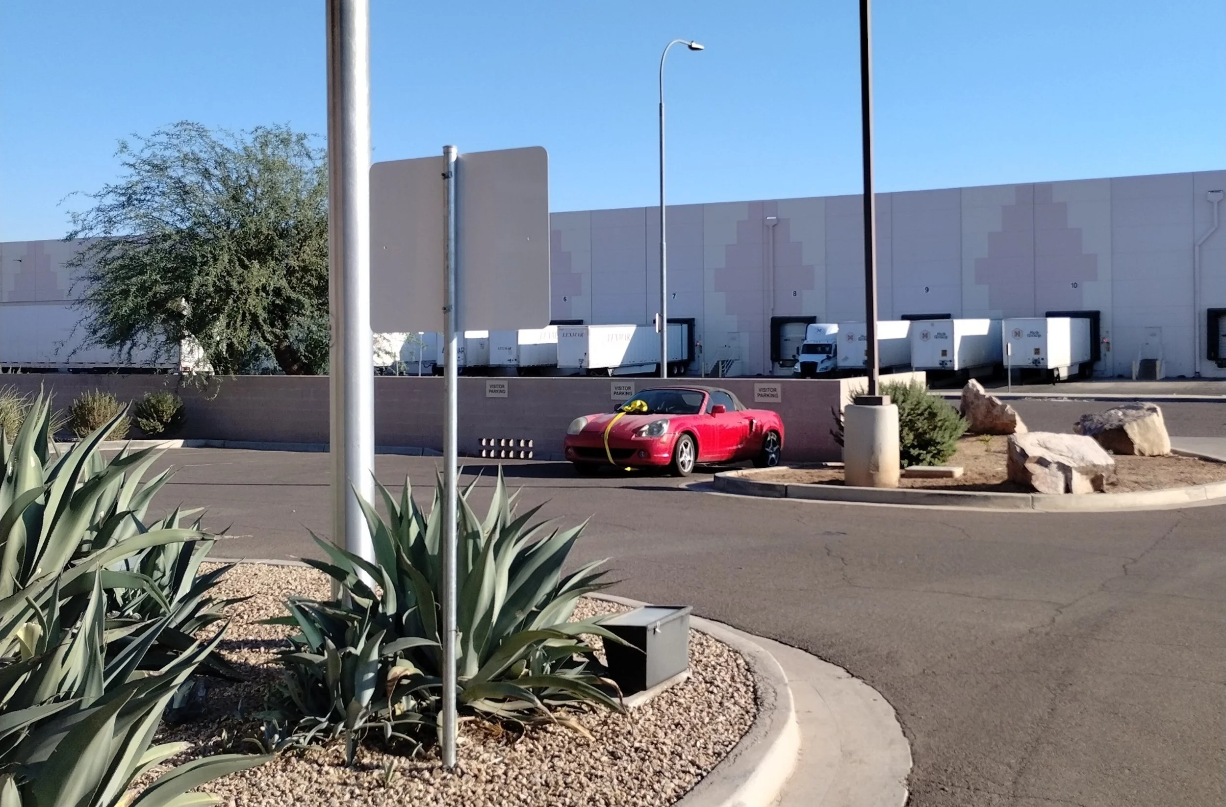
I wish that was a bow and this was the Lexus December-to-Remember sales event
The next day was uneventful, since I only had to tow it another 20 miles or so.
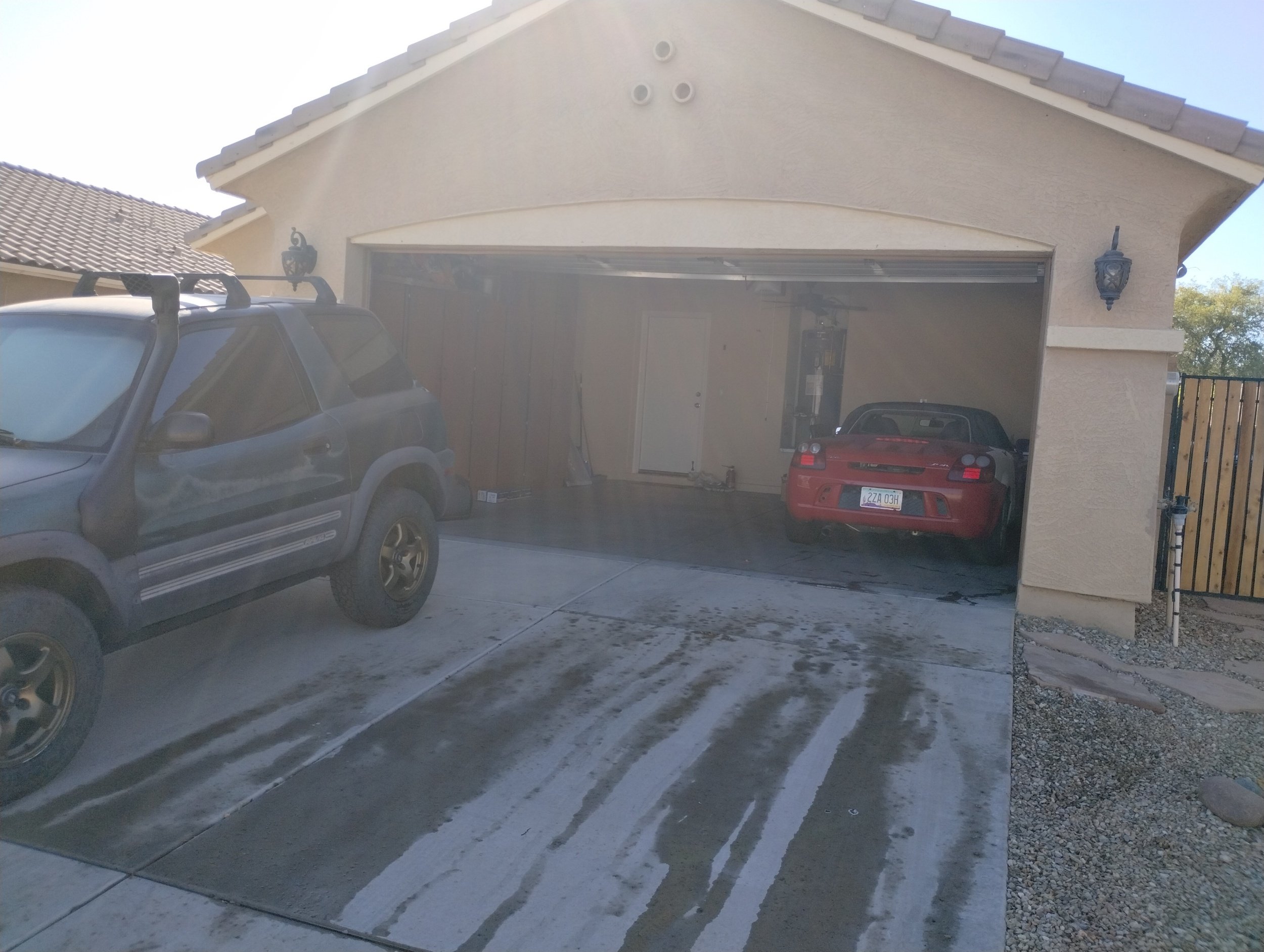
MR2, meet MR2.
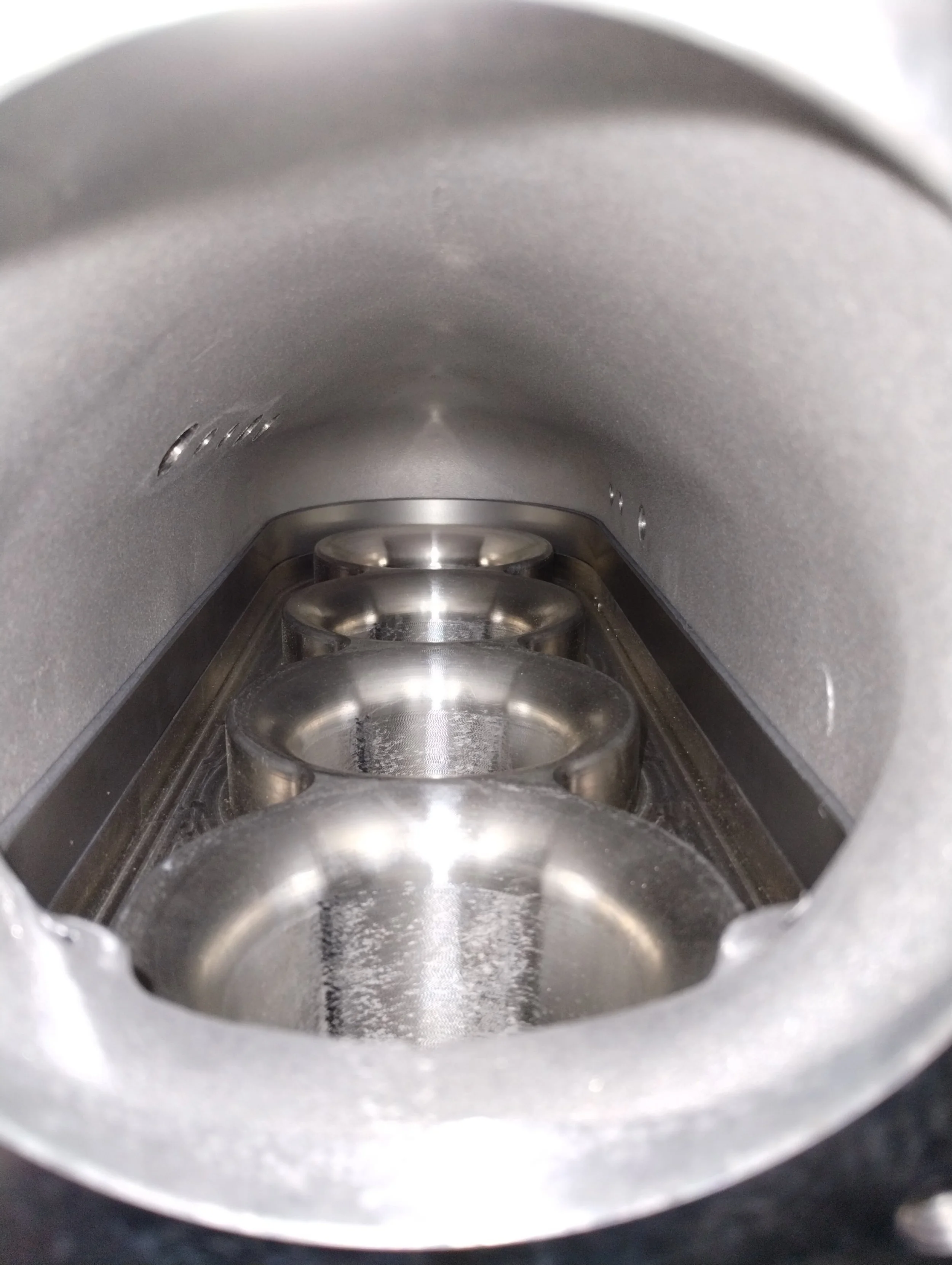
With no time to waste, I had to start disassembling. First was, of course, to drain all of the fluids. The engine oil smelled absolutely awful, but looked fine. I didn’t see any metal particles, which was too bad, I was hoping for something catastrophic. I checked, and no windows around the block. Looked completely fine. Even if it was fine, I wasn’t planning to use it.
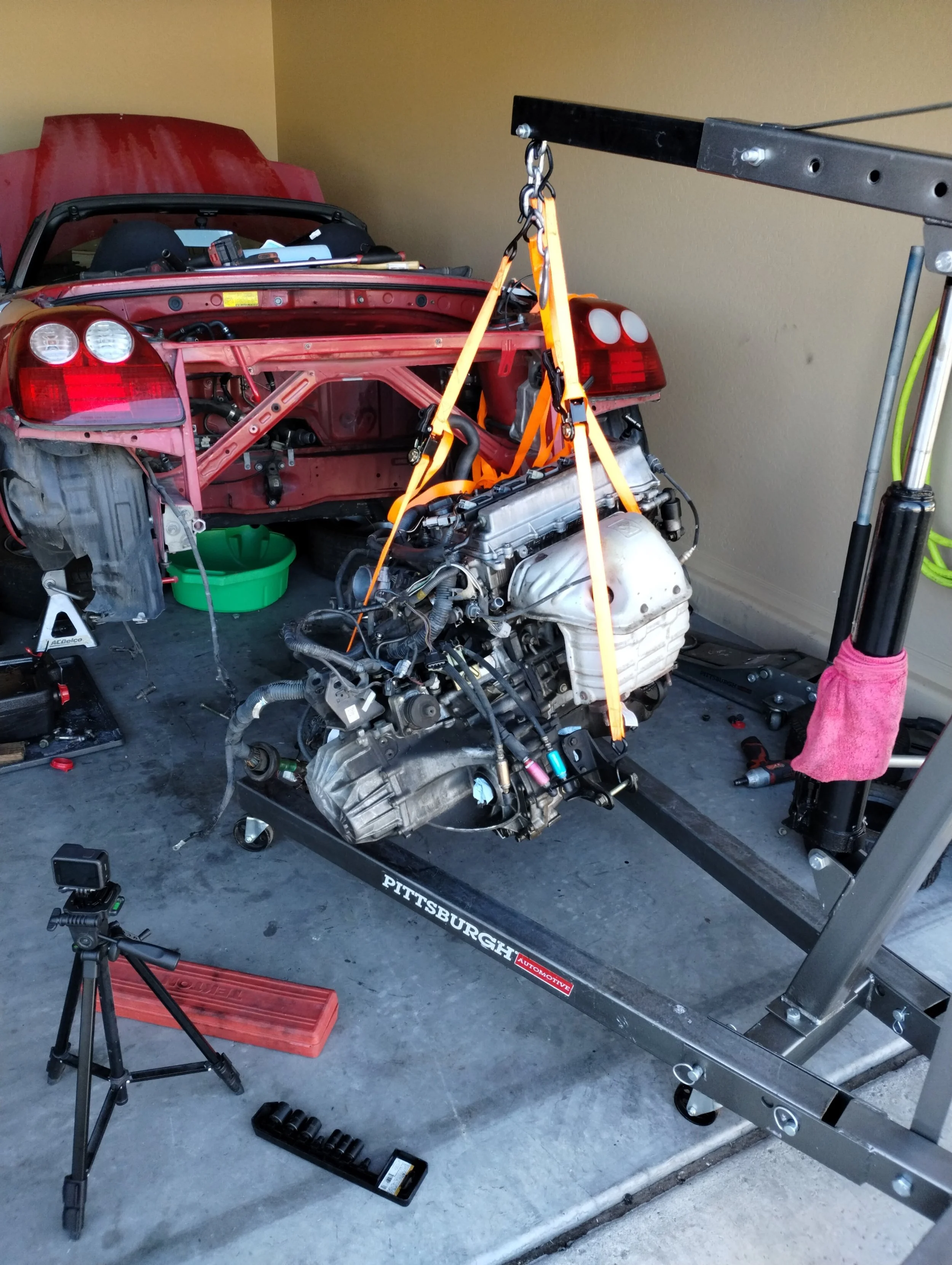
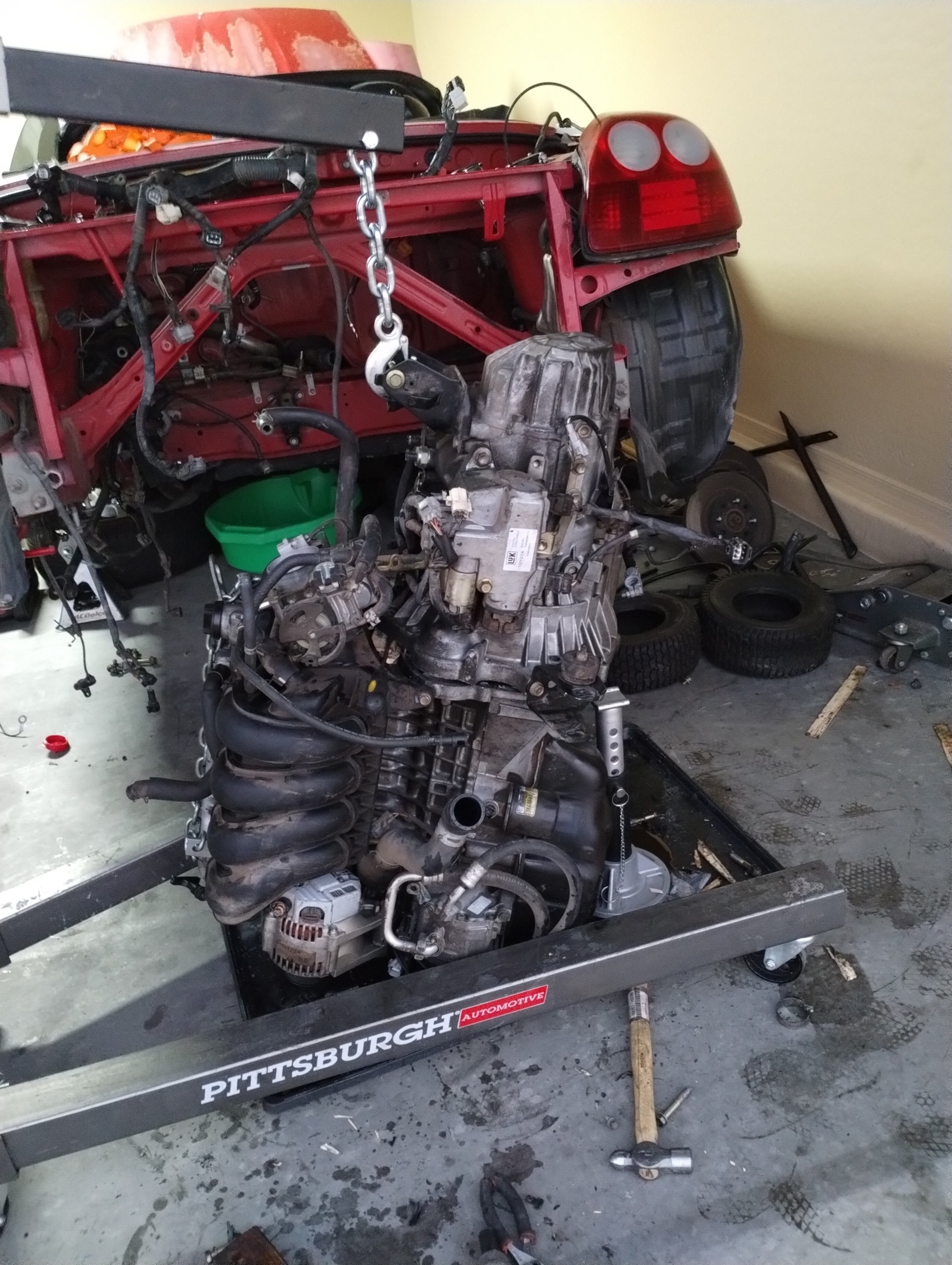
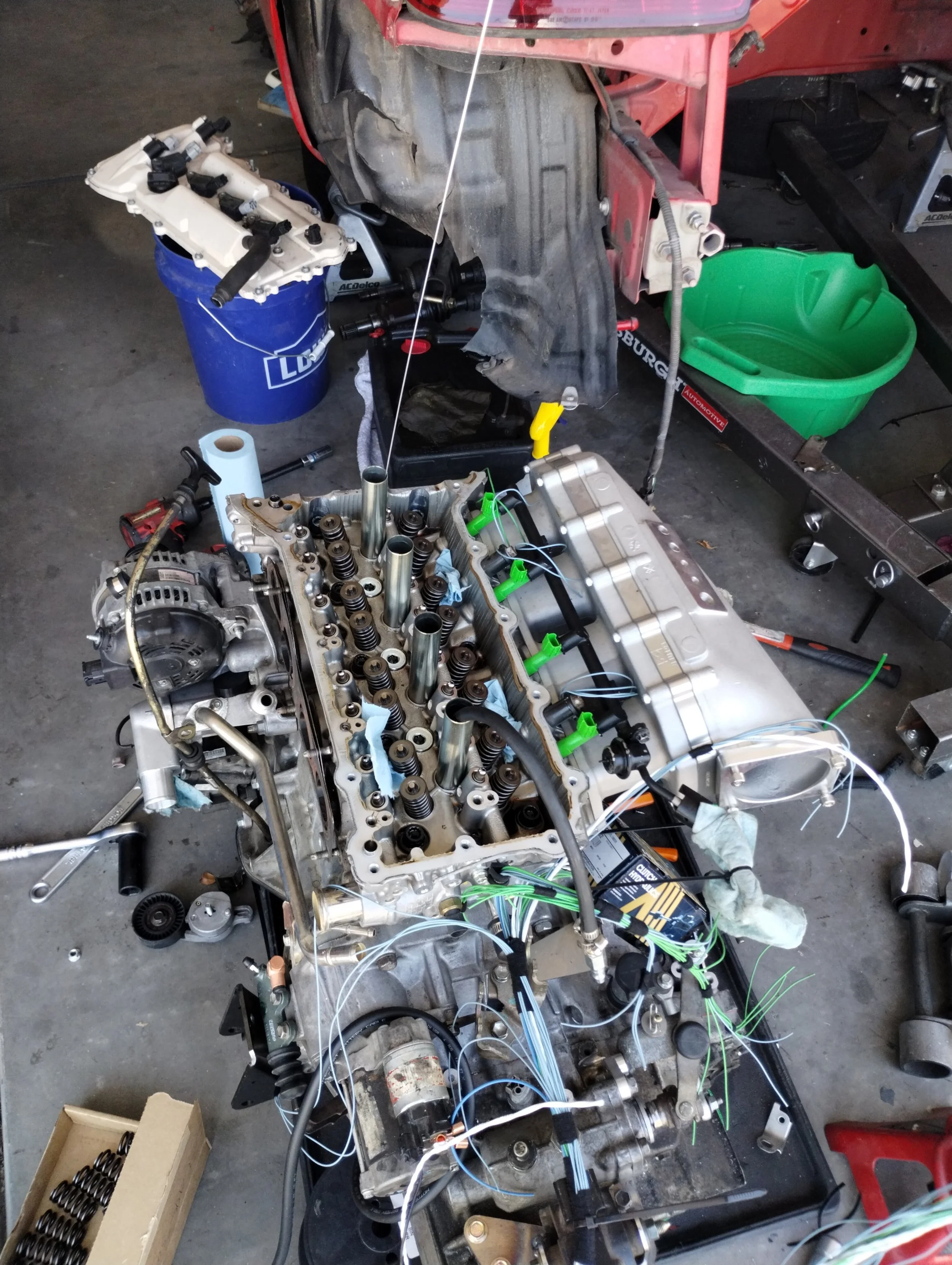
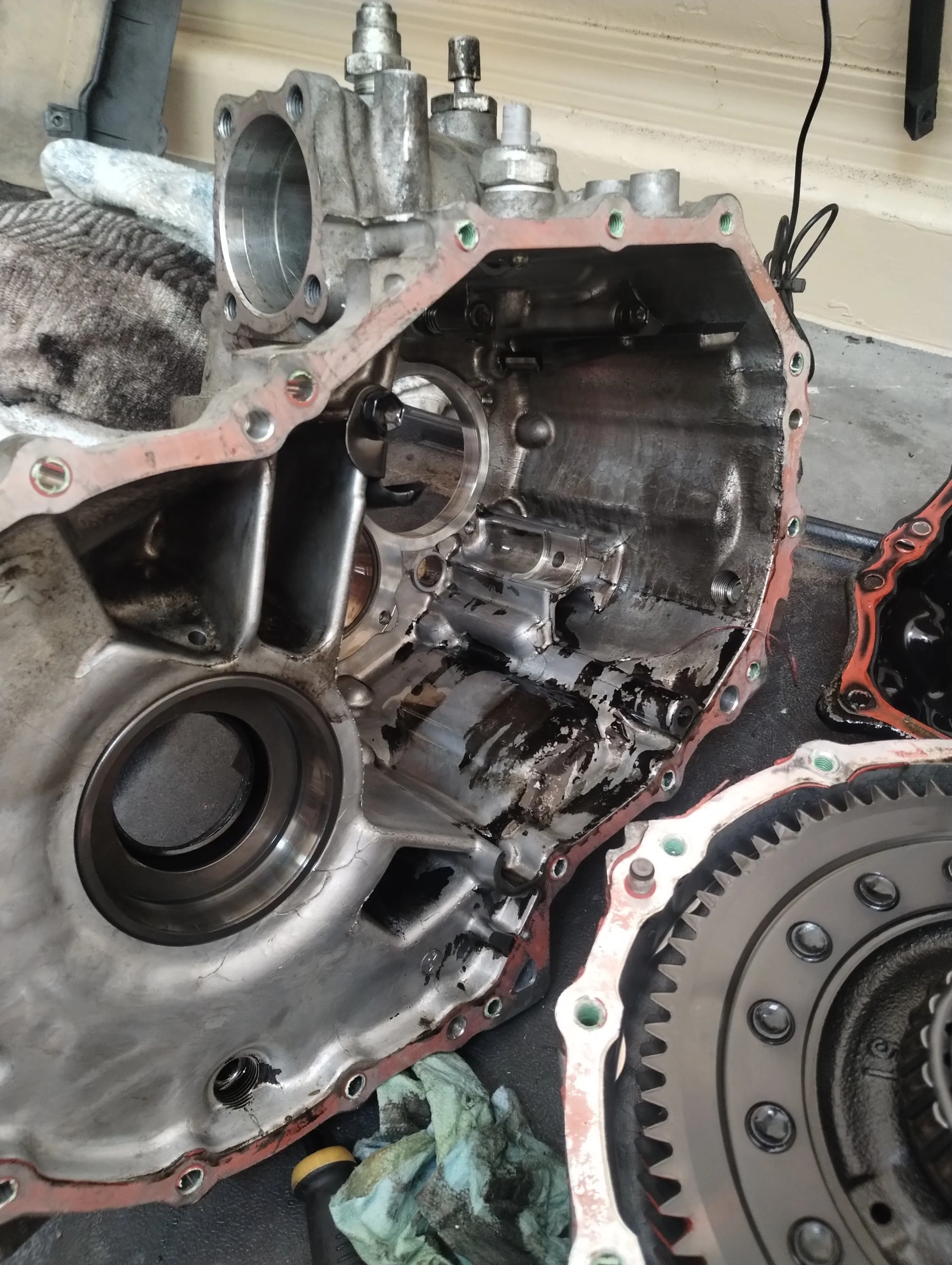
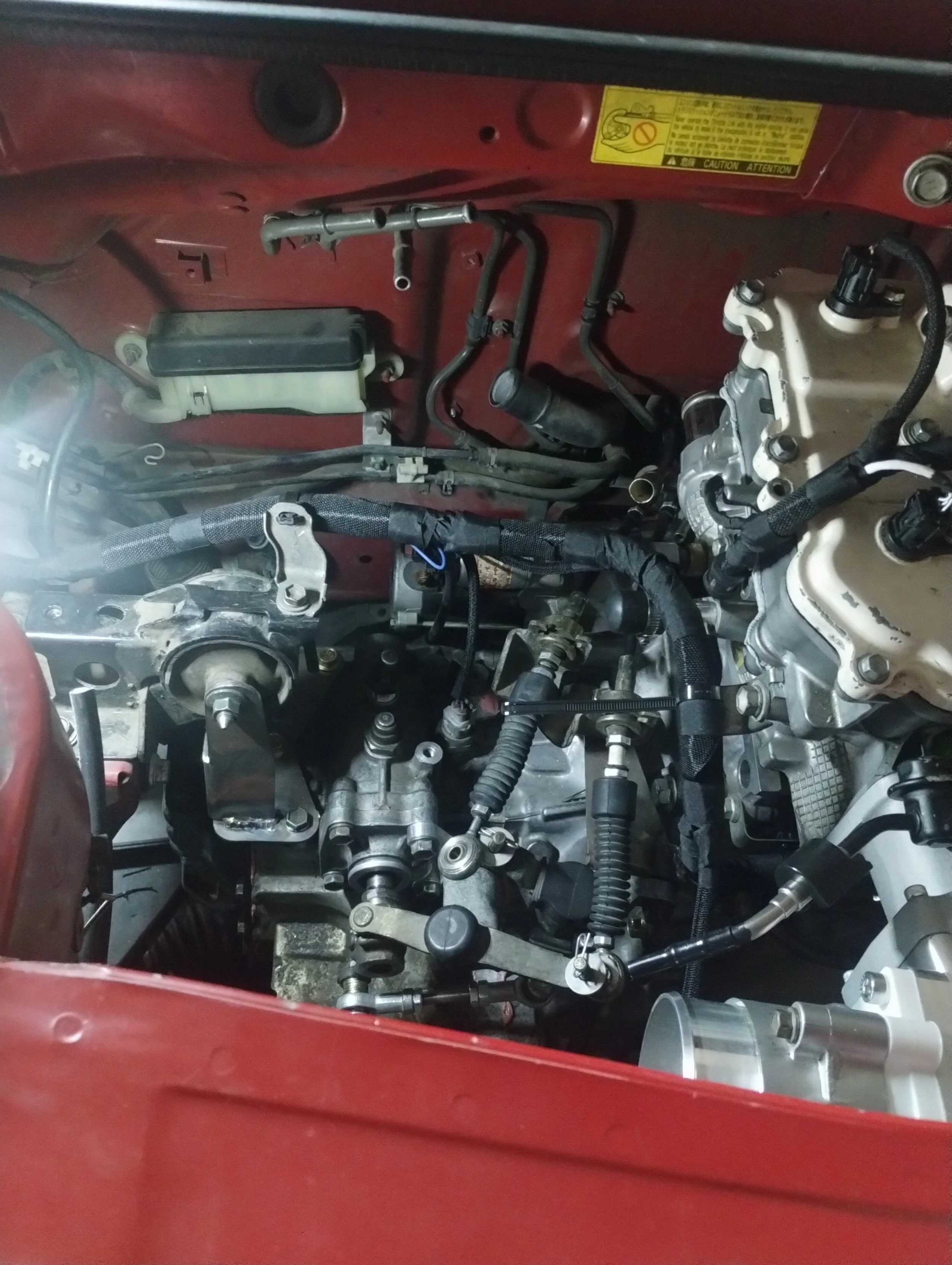
Fairly straightforward, nothing noteworthy. Again, coming from SW20s, this car is SO easy to work on. Pulling the engine only took me about 2 hours. I had a hell of a time separating the transmission though, and ended up trying to pry them apart. At first I thought the dowels were seized, but I then realized there was a bracket mounting the throttle body to the transmission that I missed. Oops. I really wanted to take this engine apart. The circumstances around the engine halting were too abnormal for it to be just fine.
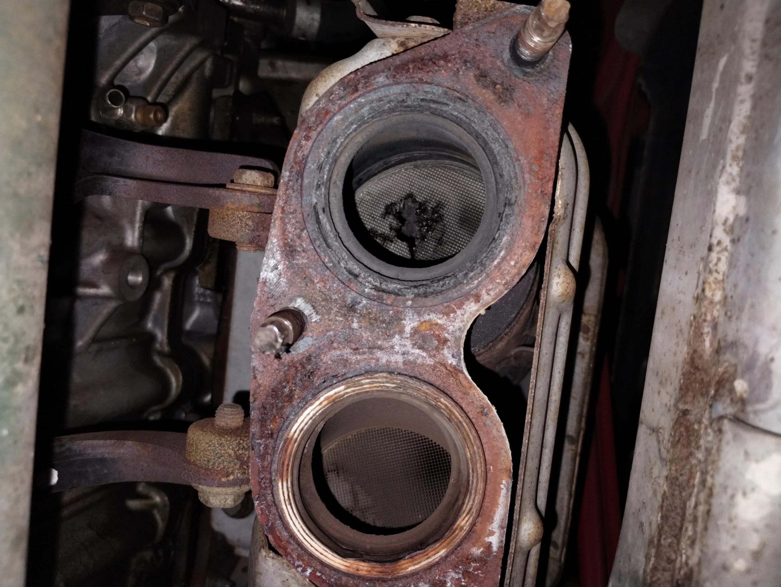
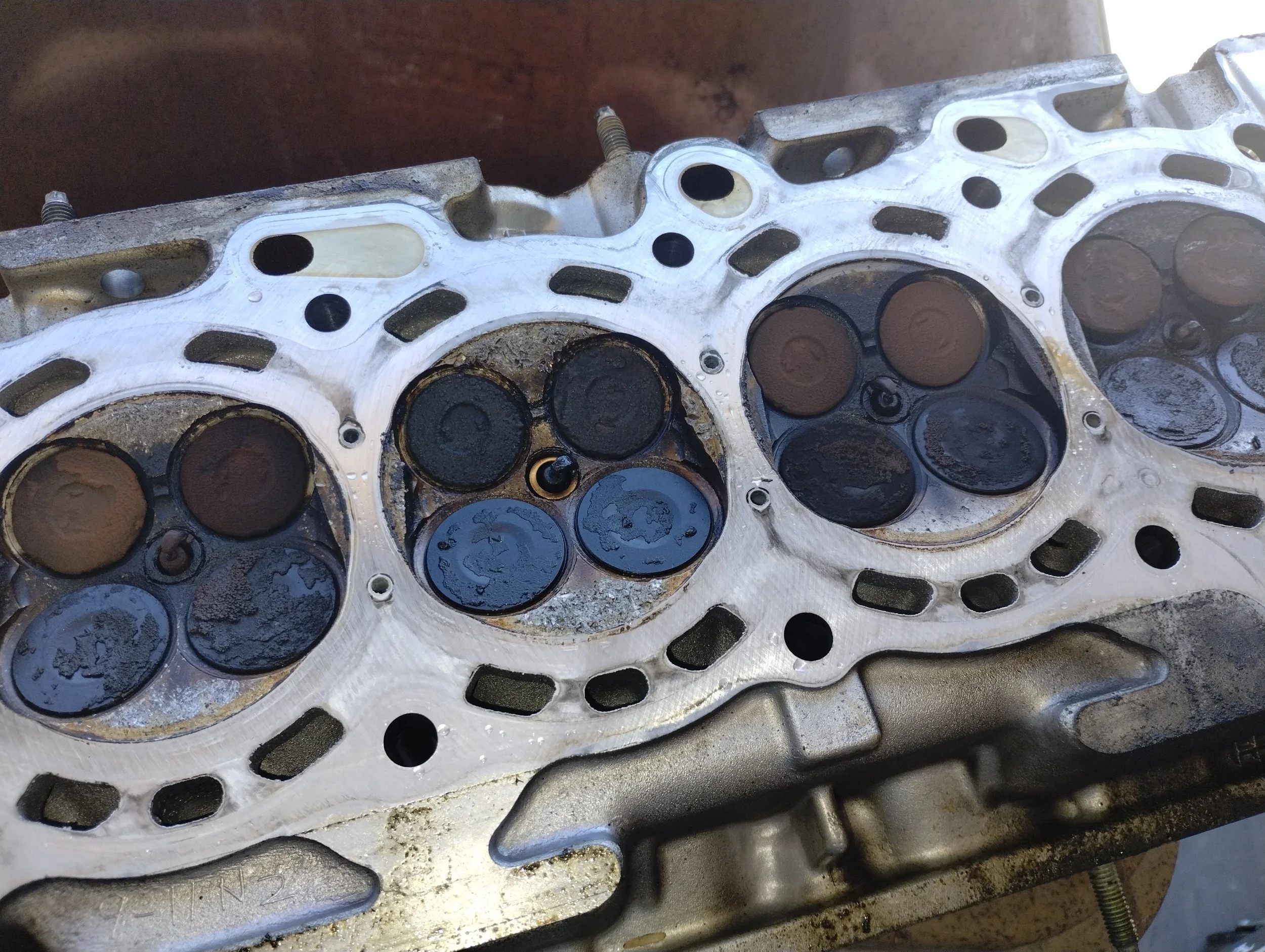
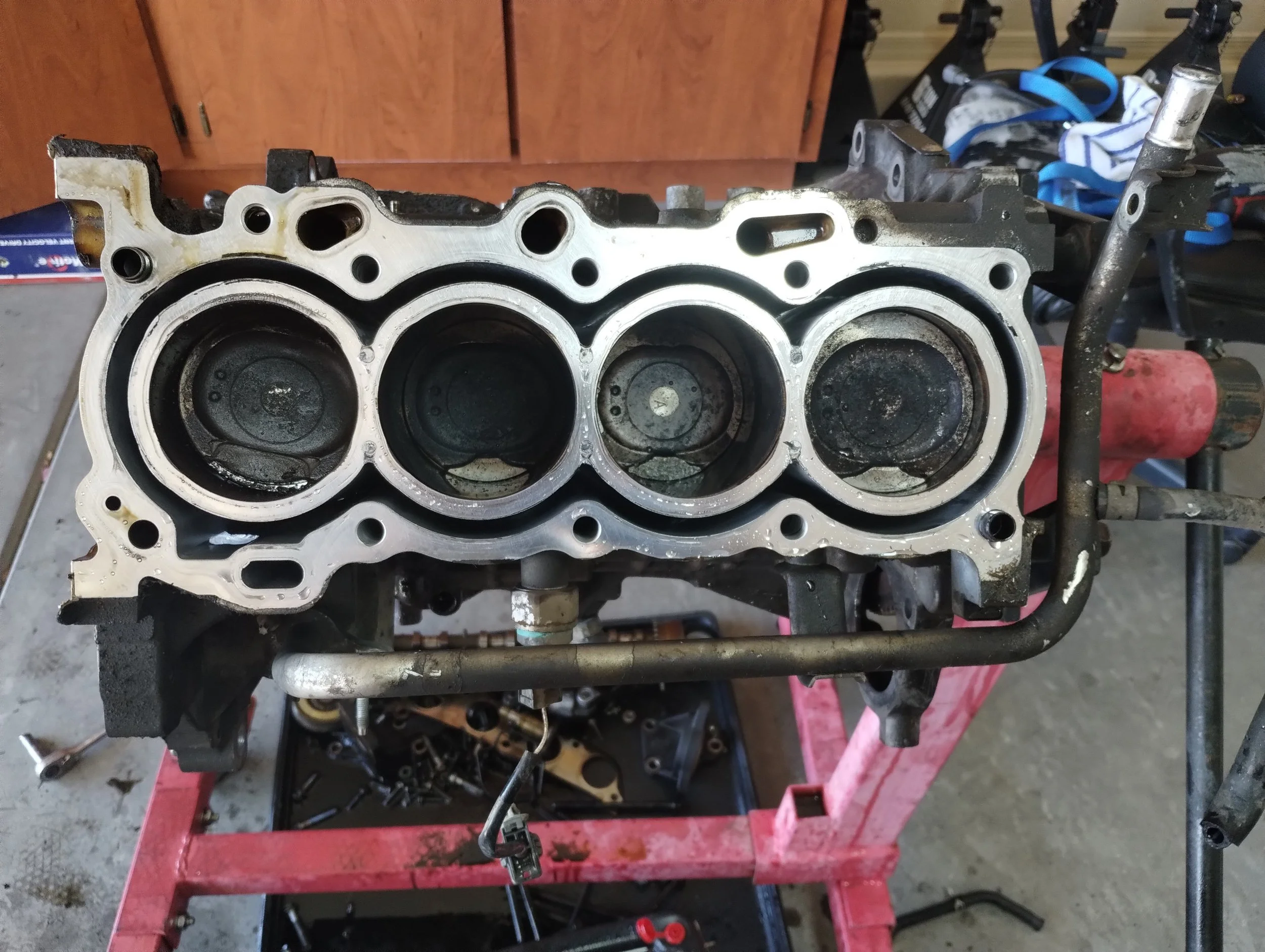
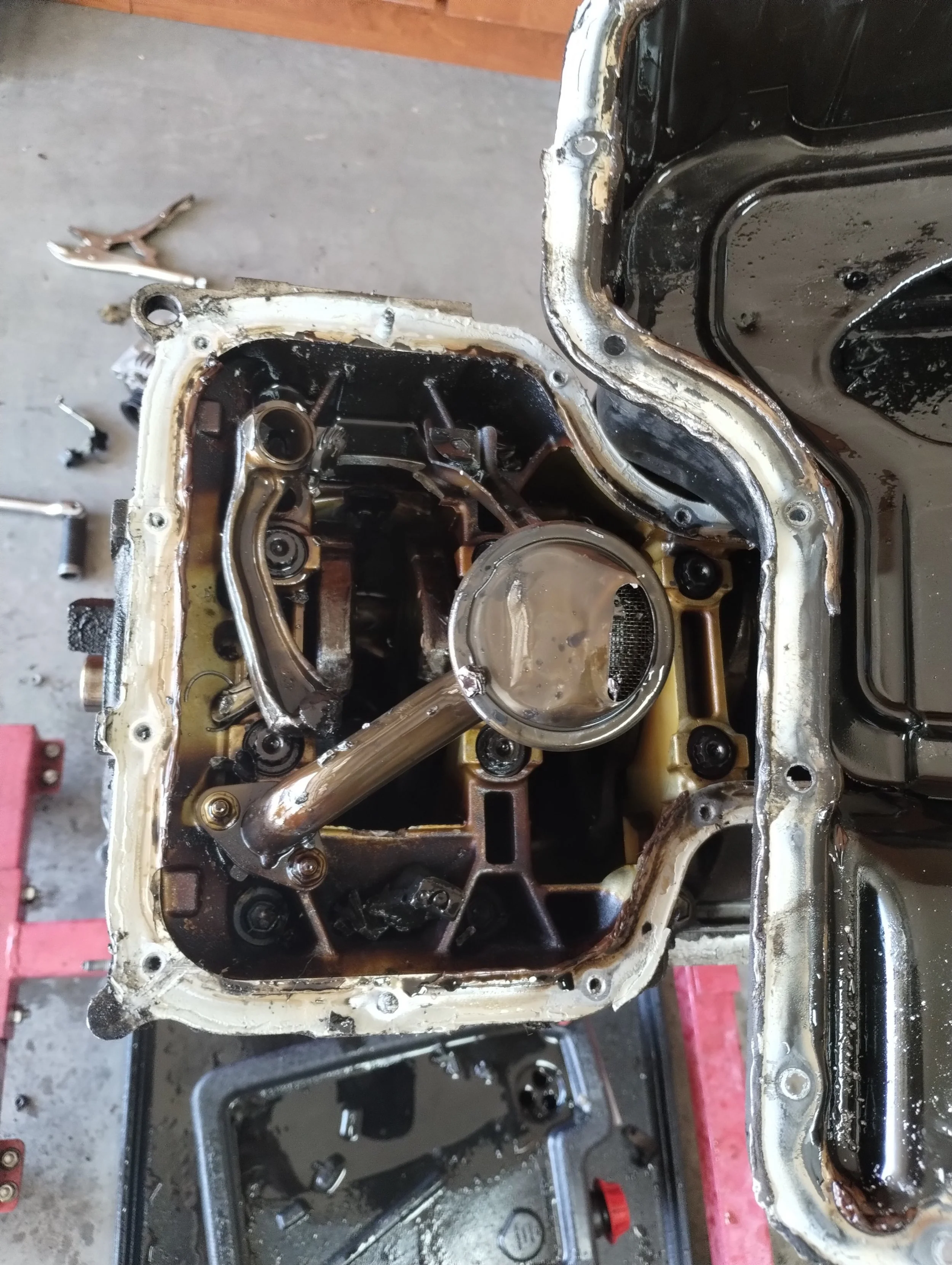
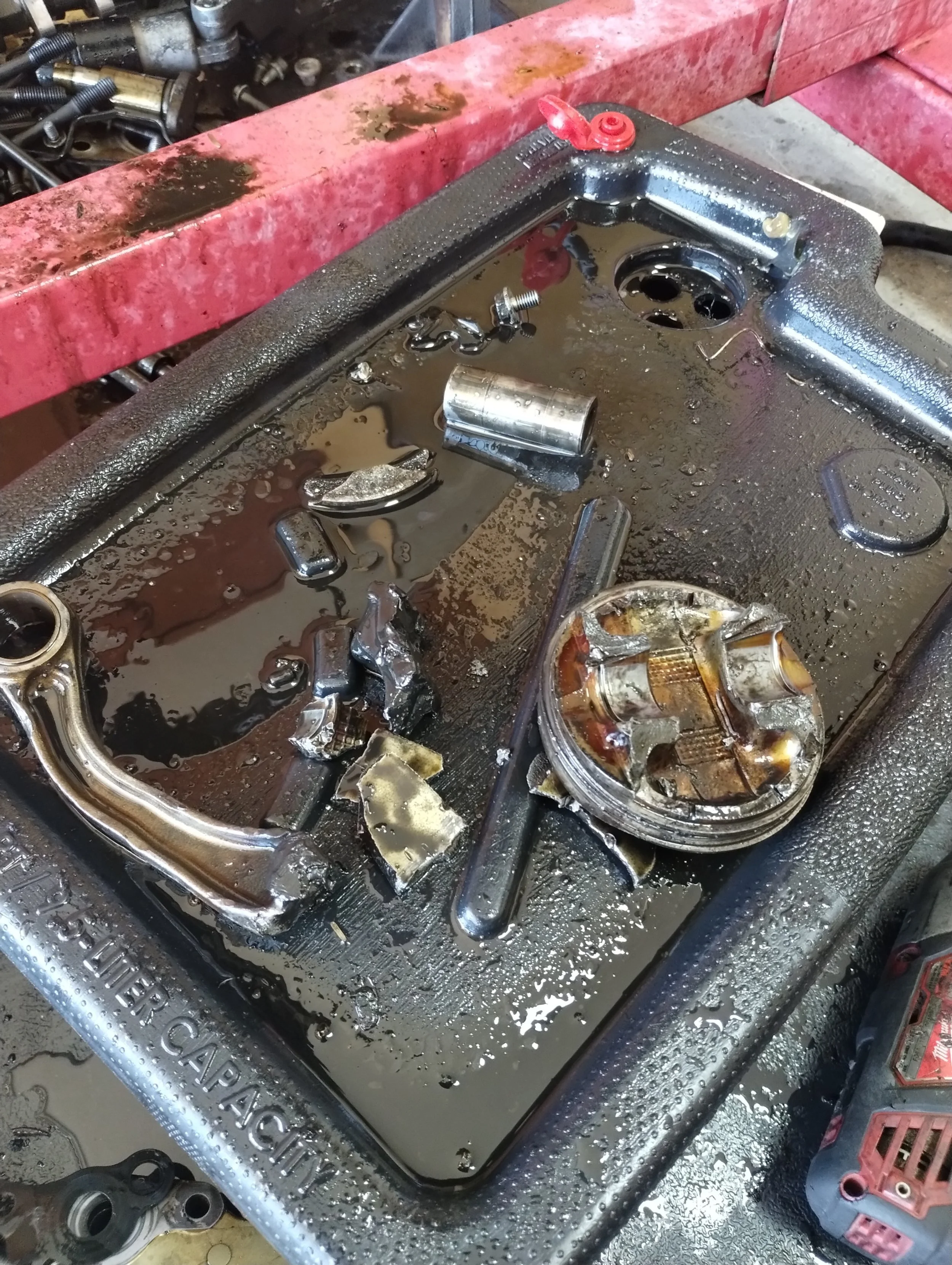
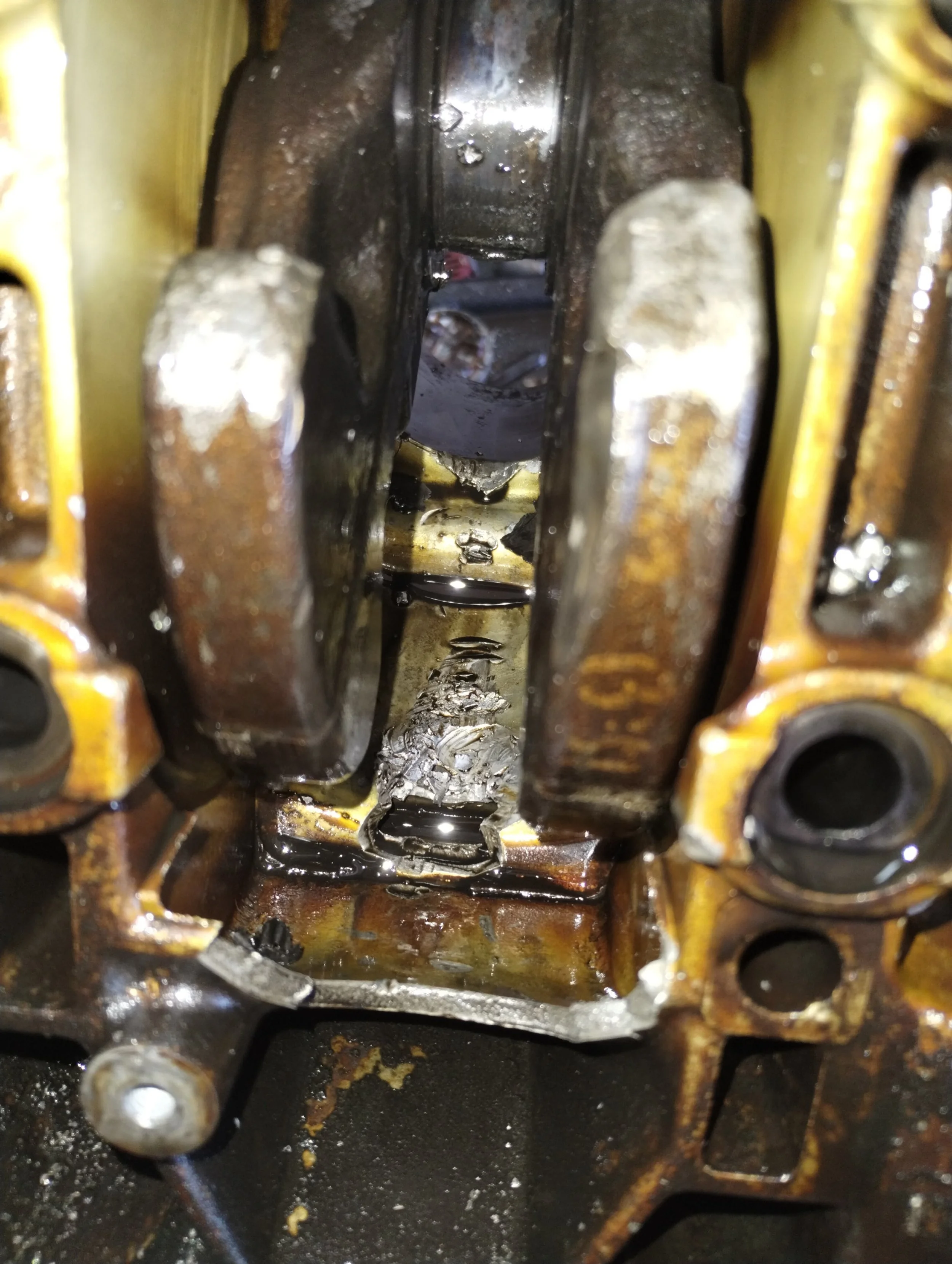
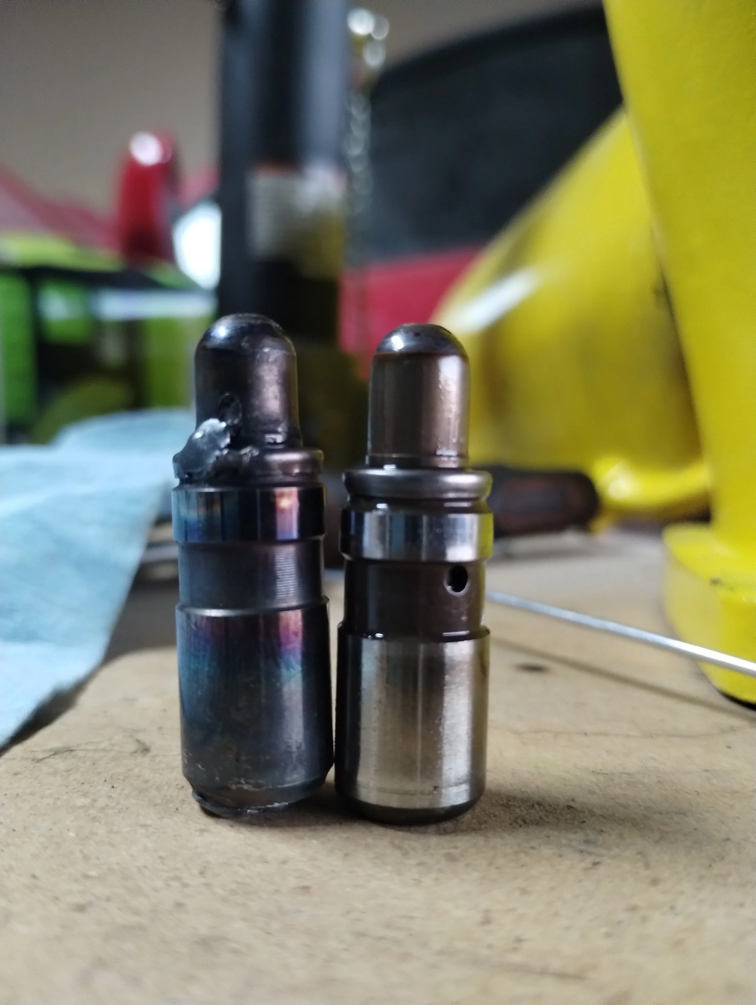
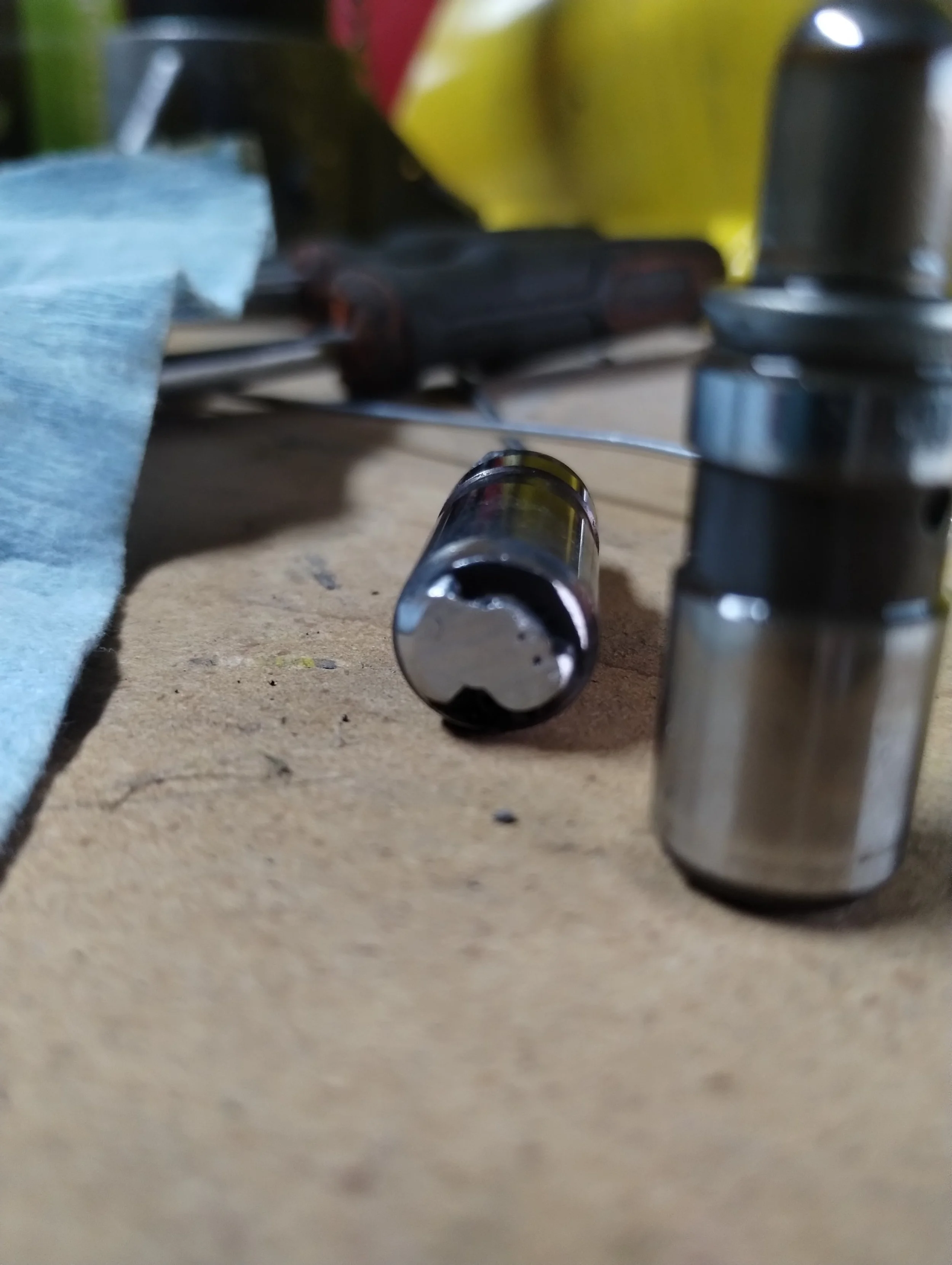
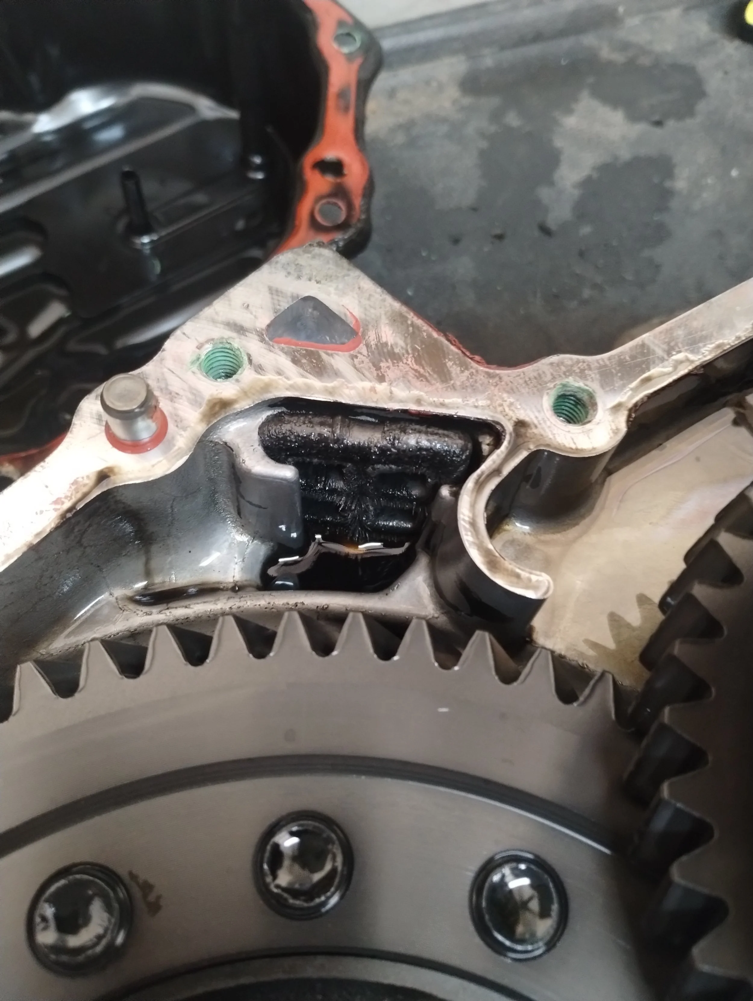
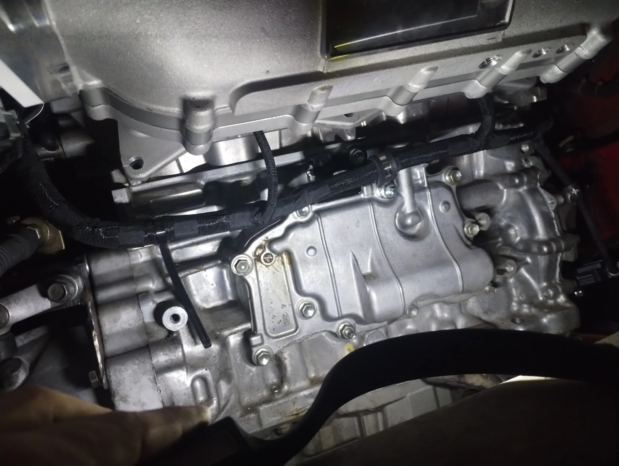
I start taking off the accessories, head, and oil pan. I found a hole in the cat, some bent valves, one damaged piston, and oh. That’s a rod. Part of one anyway. To my eyes, it appears the cylinder #1 rod bearings seized and threw the rod. It wasn’t just broken, but demolished. Same with the piston—it’s missing the skirt entirely. The oil pan was completely full of Piston McNuggets™, though I didn’t get a picture of that. I knocked a nice hole in the main oil supply, so this block is far beyond toast.
Note: to anyone who might complain that I’m just destroying this for fun, it was very clear to me that the engine was far beyond repair when I initially bought the car. There was likely nothing salvageable from this engine to begin with.
Time to get the replacement. I already had one, I just had to go get it back home.
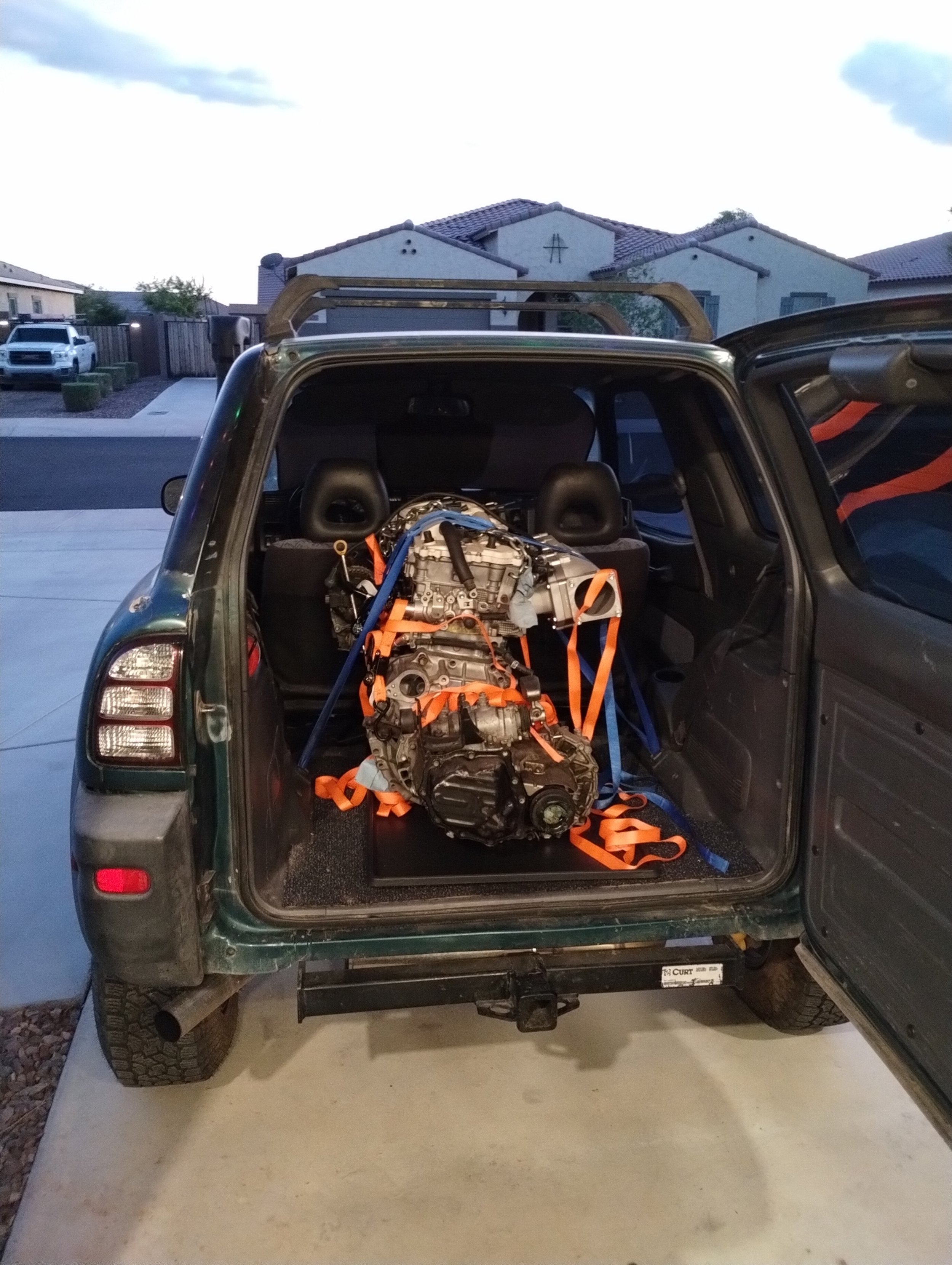
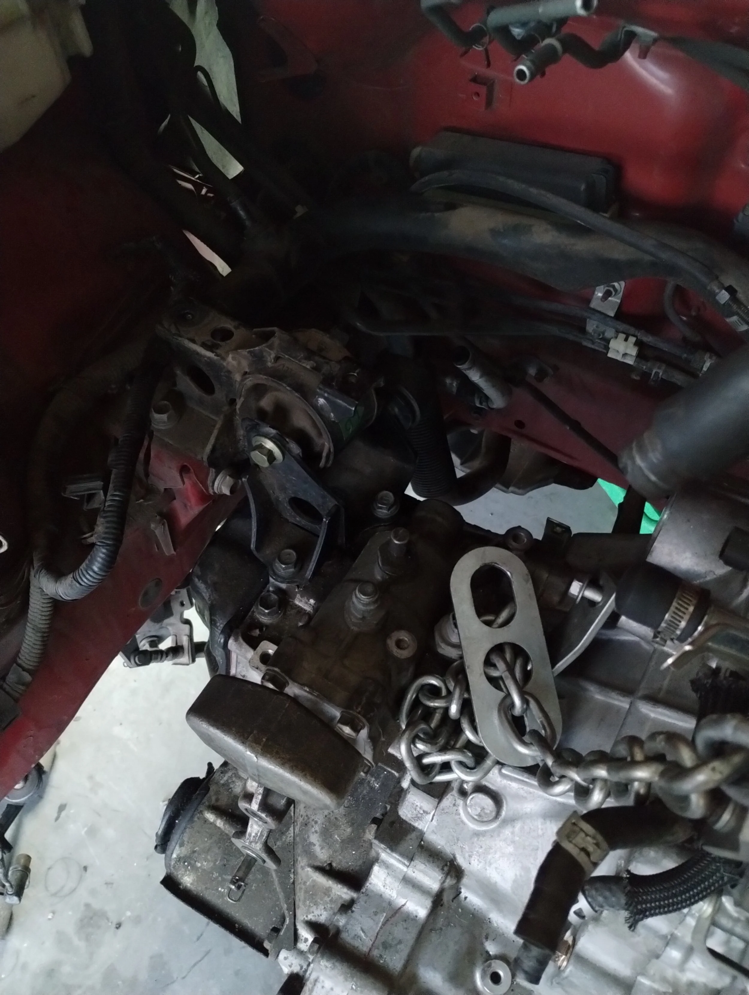
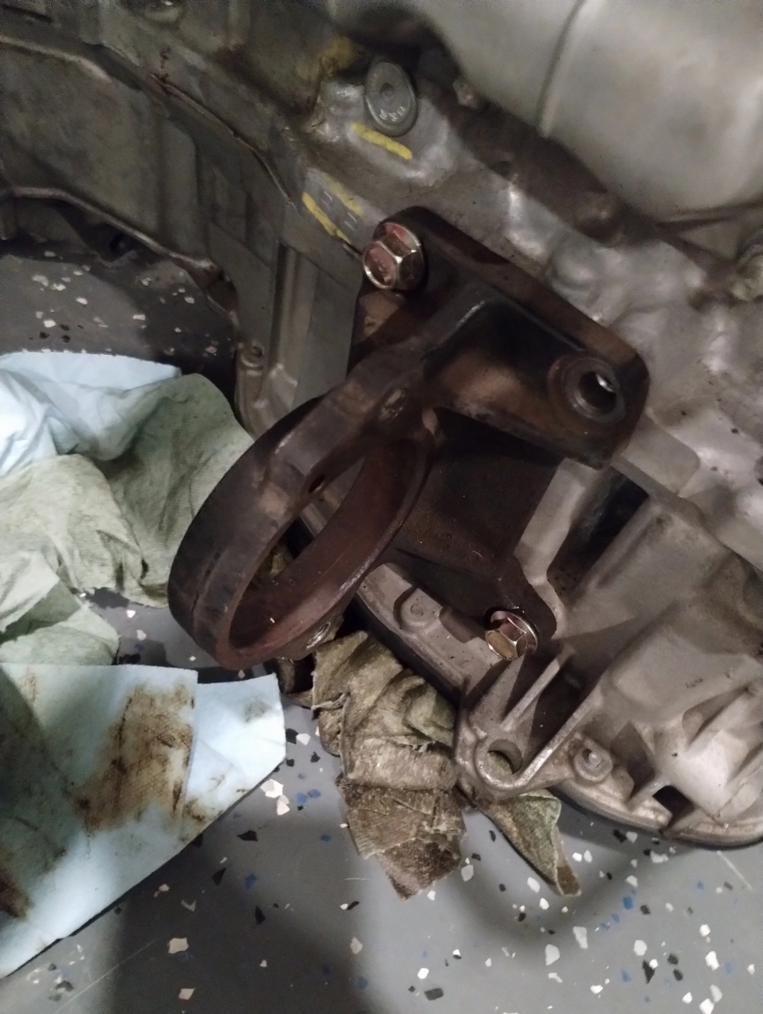
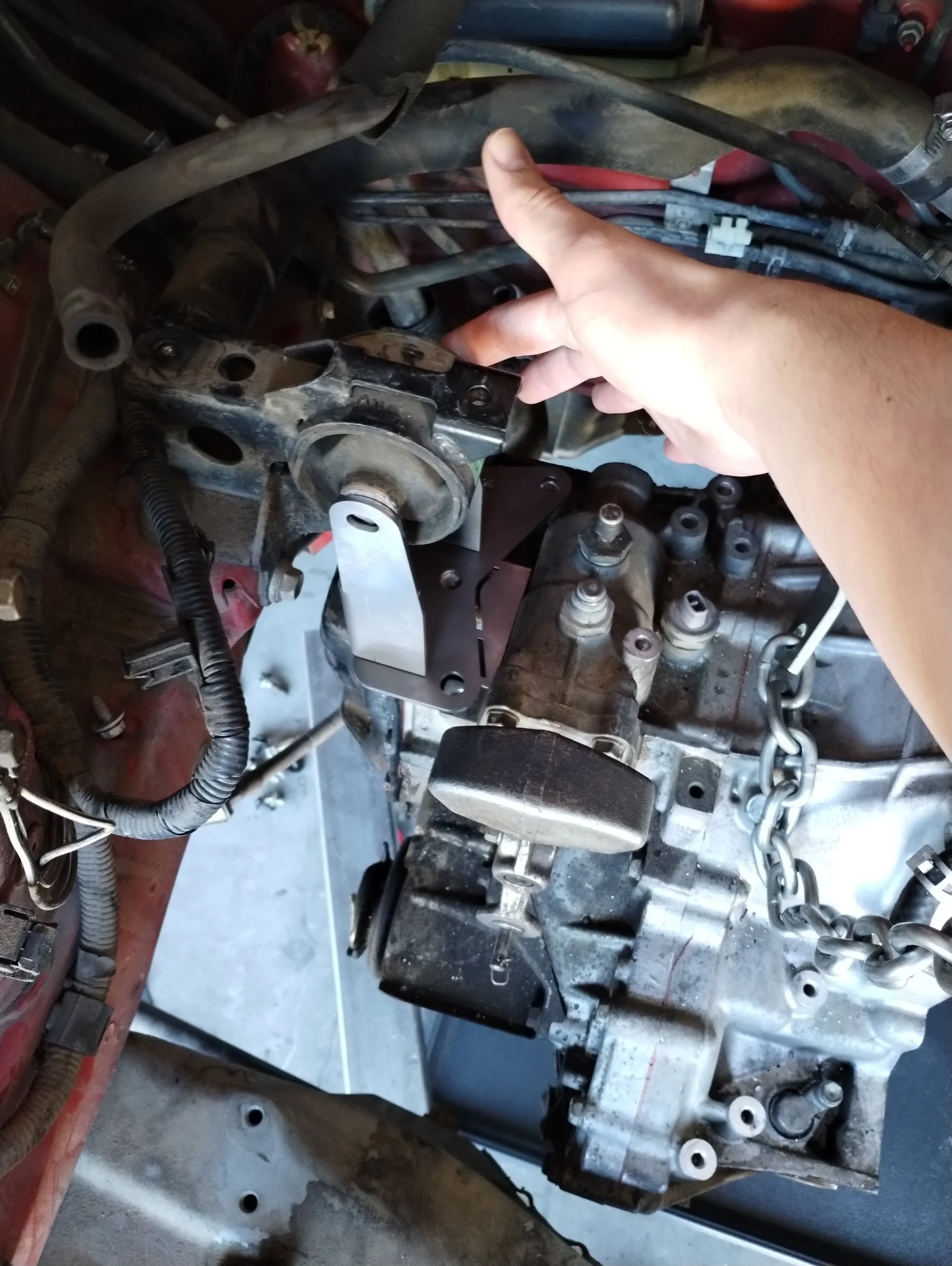
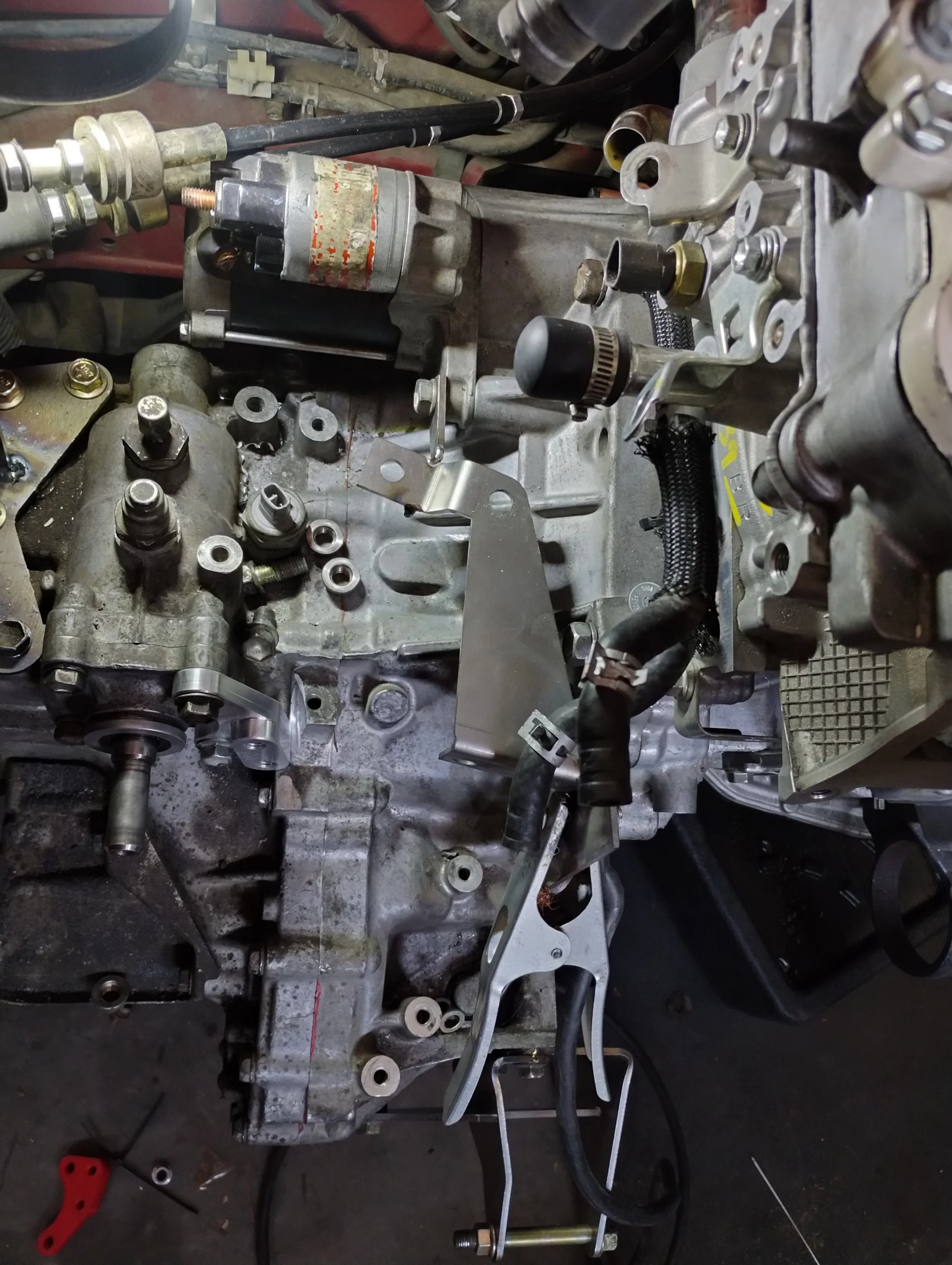
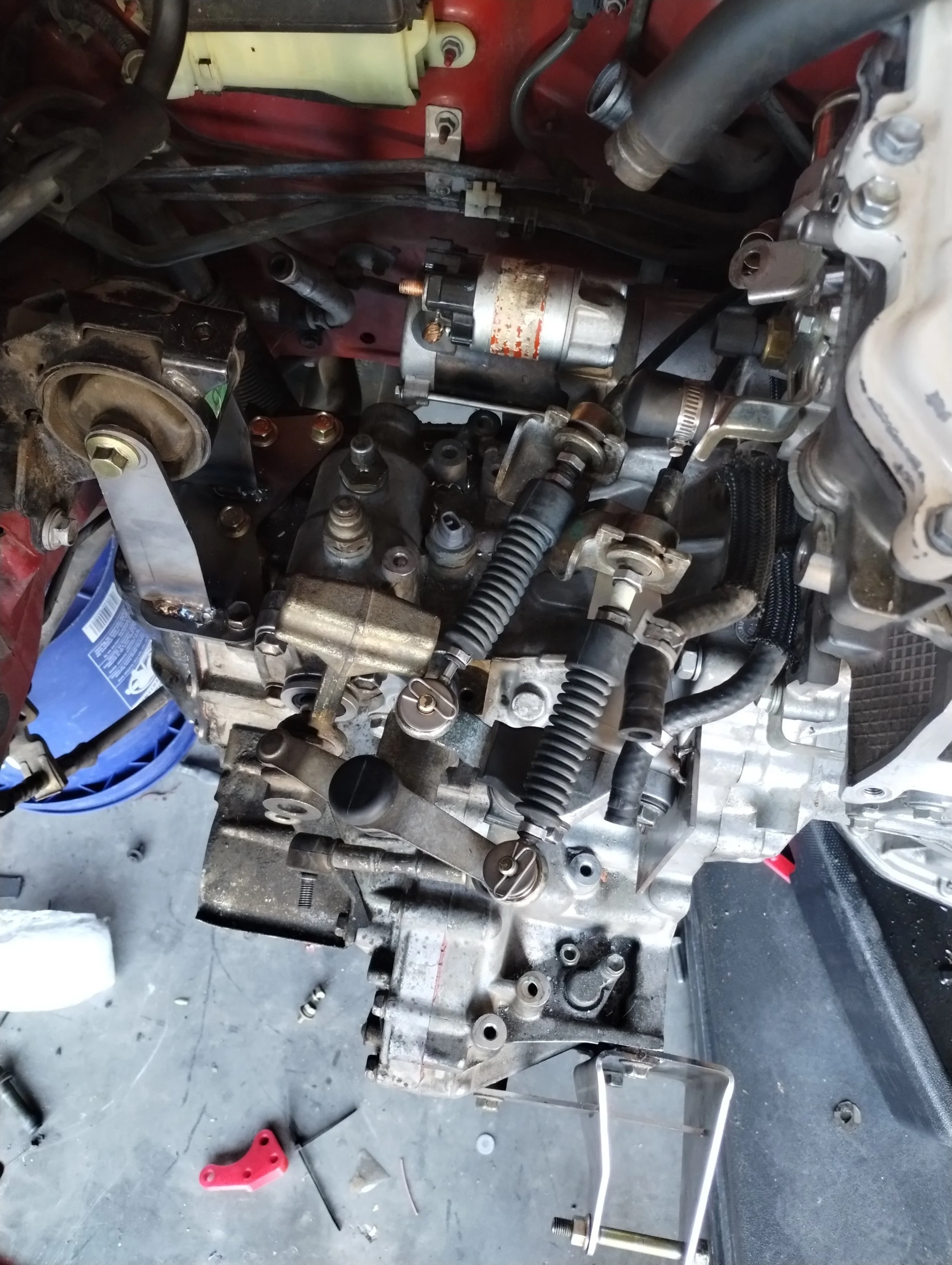
I picked up my 2AR with my other 2AR. Getting it in was pretty straightforward. I’m using the right side mount from Frankenstein Motorworks, and as a temporary holding solution, I installed a factory Scion tC1 left side mount. It’s surprisingly close, but off enough to be unusable. It holds the engine cocked too far up and pushed rearward. This should be a pretty straightforward mount to make, then the other two can quickly follow suit.
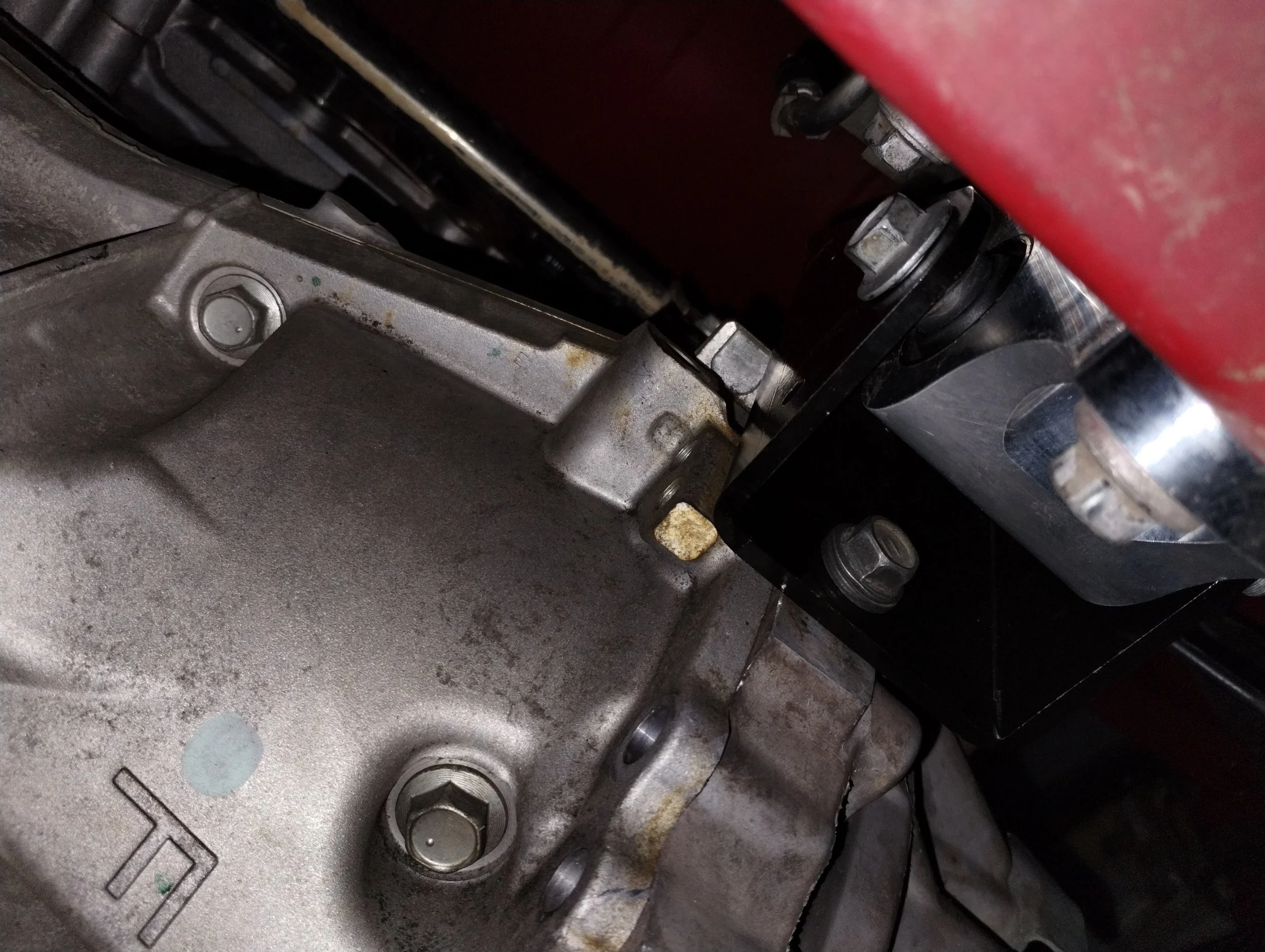
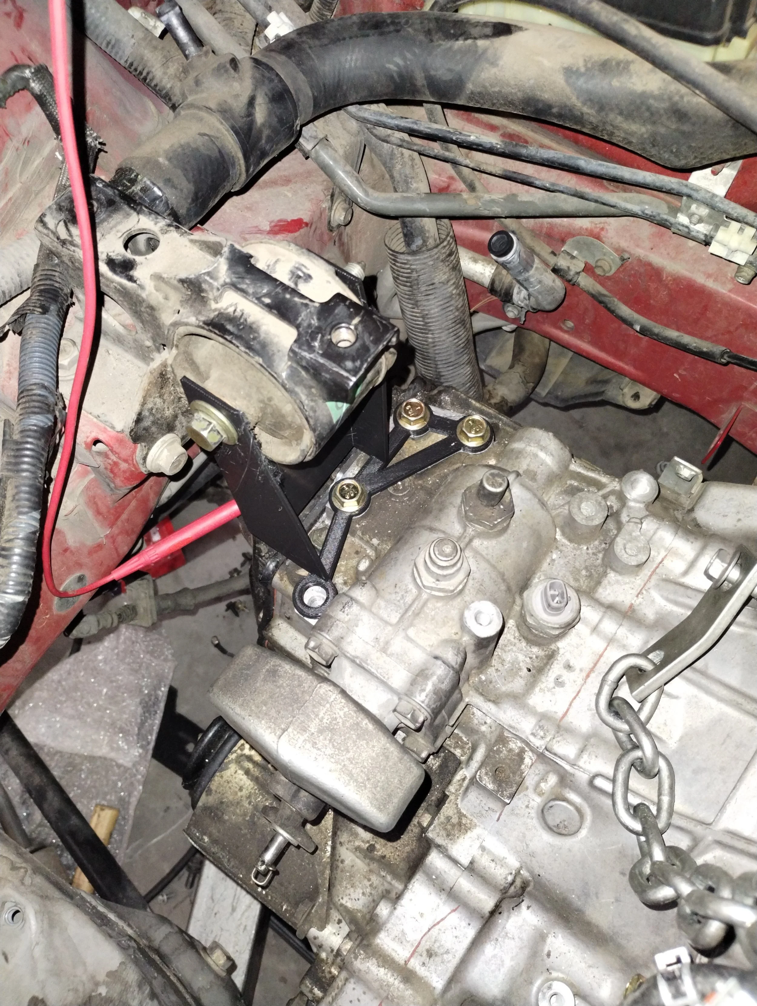
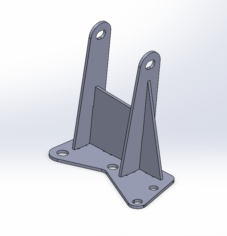
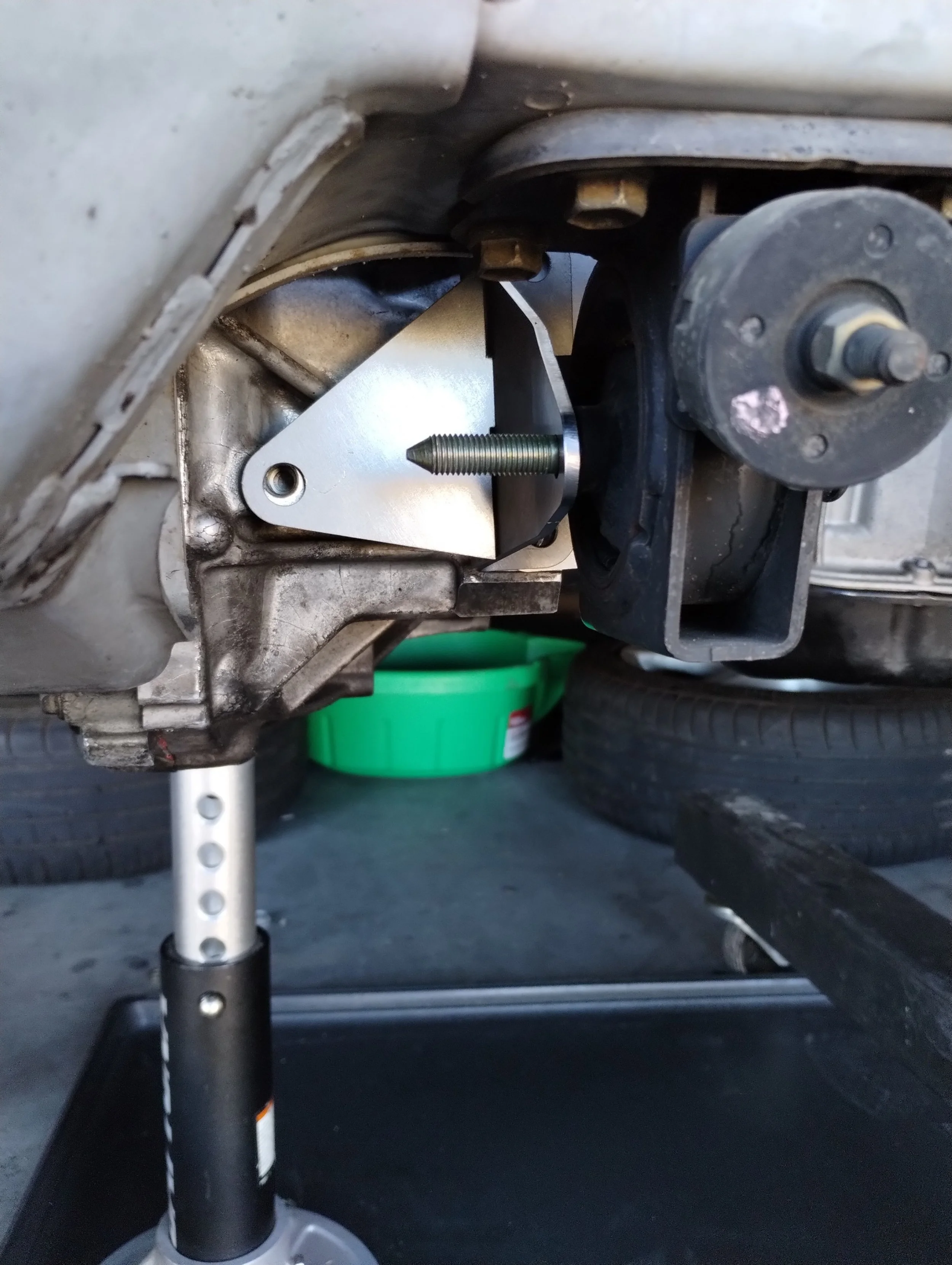
I started by trying the Frankenstein Motorworks EB60 front mount. I got the lower bolt hole on the bracket bolted to the transmission, and that lined up well enough that I only needed to add the upper bolt hole. That settles two out of the four mounts, and the rest should be easy. I looked for some left side mounts, and found nothing from Toyota that would work, which wasn’t a huge surprise. I started by measuring then 3D printing a few test pieces to make sure I had all of the bolt holes correctly positioned. After this, the rear mount was slightly harder, but still easy. I debated getting something CNC or sheet metal, and I settled on a welded sheet metal construction, and sent the finalized designs over to Send Cut Send. After talking with Marc, the biggest question of fitment was whether there was clearance to the rear crossmember. This is a known problem with E153 swapped Spyders, where there are two points of contact, the left side frame rail and the rear crossmember. An E350 is a fair bit narrower than an E153, and the left side clearance is plentiful. It is also smaller in the differential area, but not by as much. Luckily, that’s a non-issue here, and there’s clearance all around.
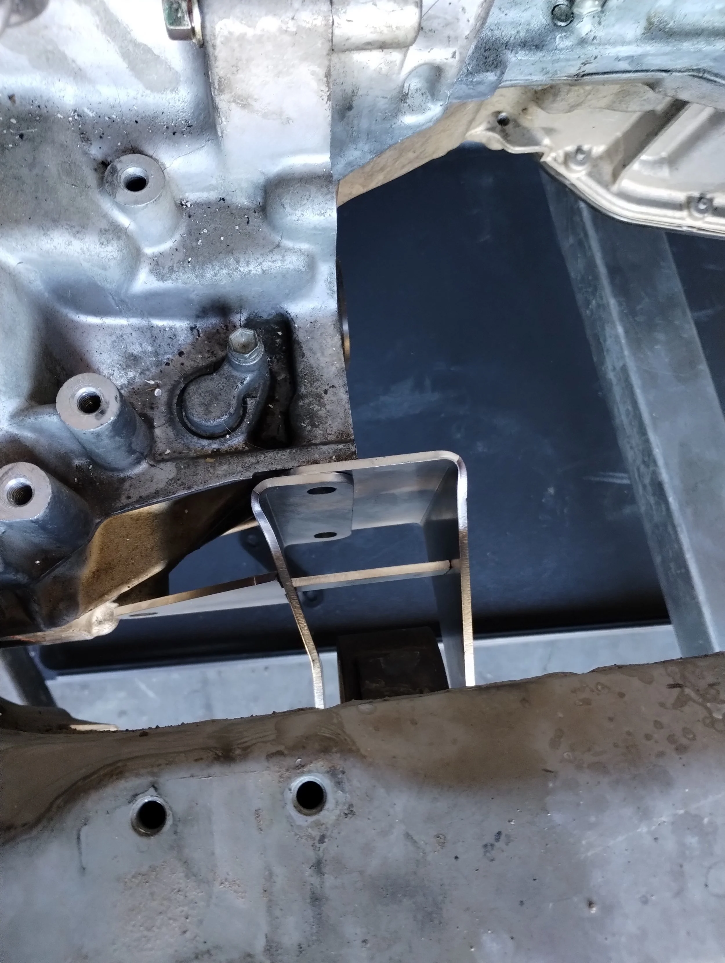
Everything lined up correctly, though I should’ve also had these bolted down to the transmission to prevent any warping. Remeasuring everything, I was happy with where it sat.
With the mounts out of the way, it’s a good time for weight reduction. This car came with an aftermarket soft top, and whoever installed it absolutely mangled the frame. The tubes were kinked, none of the brackets were properly attached, and it was extremely stiff to extend and retract. I didn’t feel too bad about lopping it all off. I got out the angle grinder out and cut off everything I deemed unnecessary.
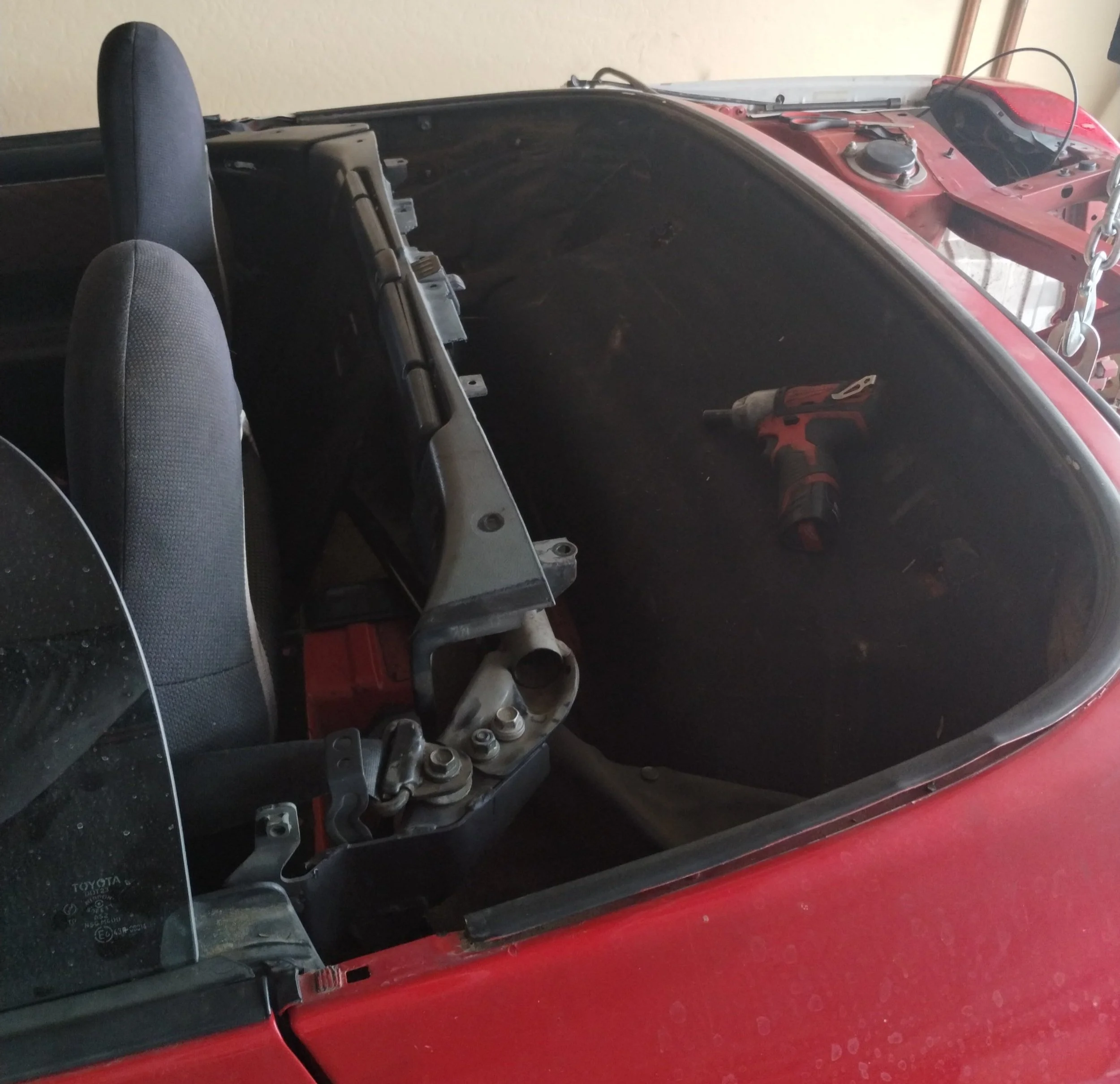
This will give me a nice parcel shelf.
That saved a good chunk of mass. I didn’t weigh it but the internet says around 30lb. I thought about running with no top, or buying an aftermarket hardtop, but Erik Seastead talked me into buying an OEM hardtop. J-Spec happened to have the perfect hardtop for this build. Bad paint, it matches the rest of the car.
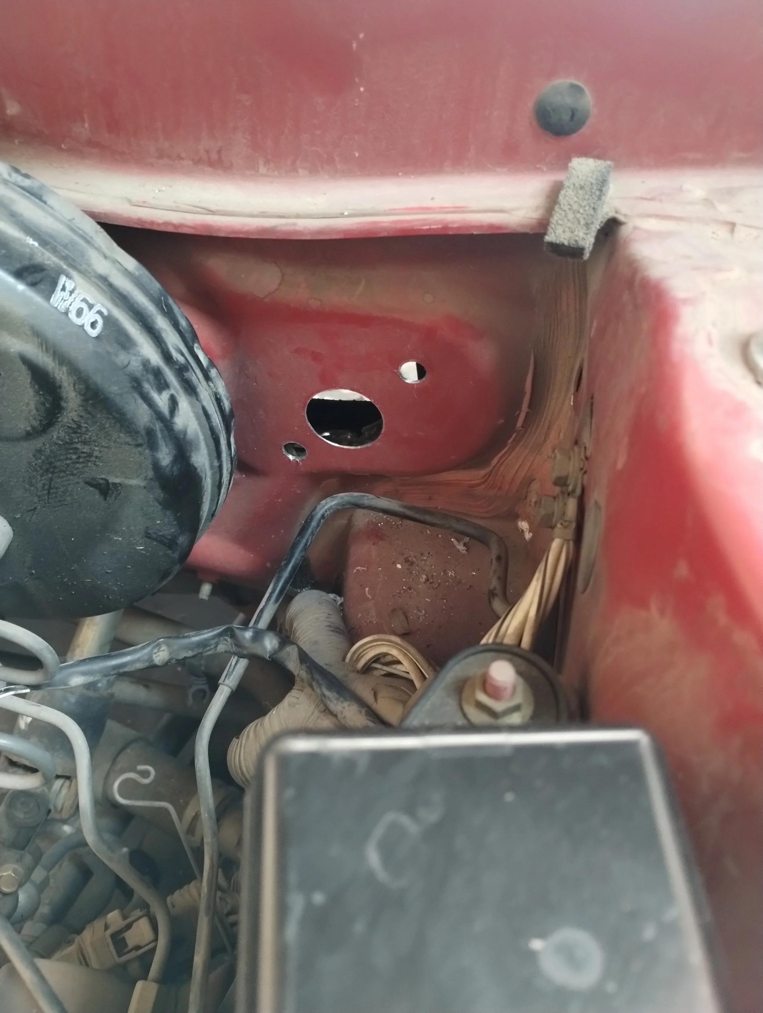
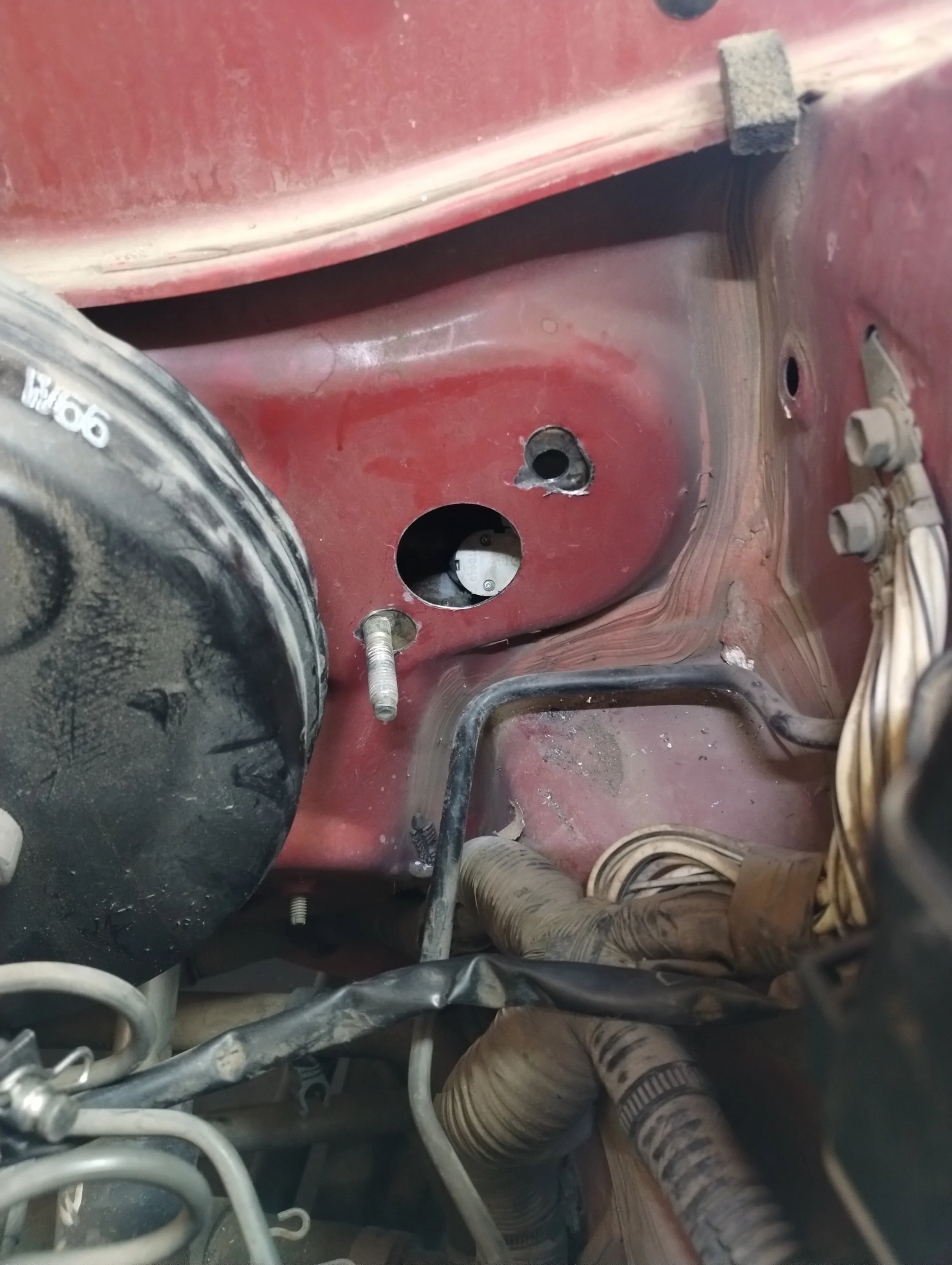
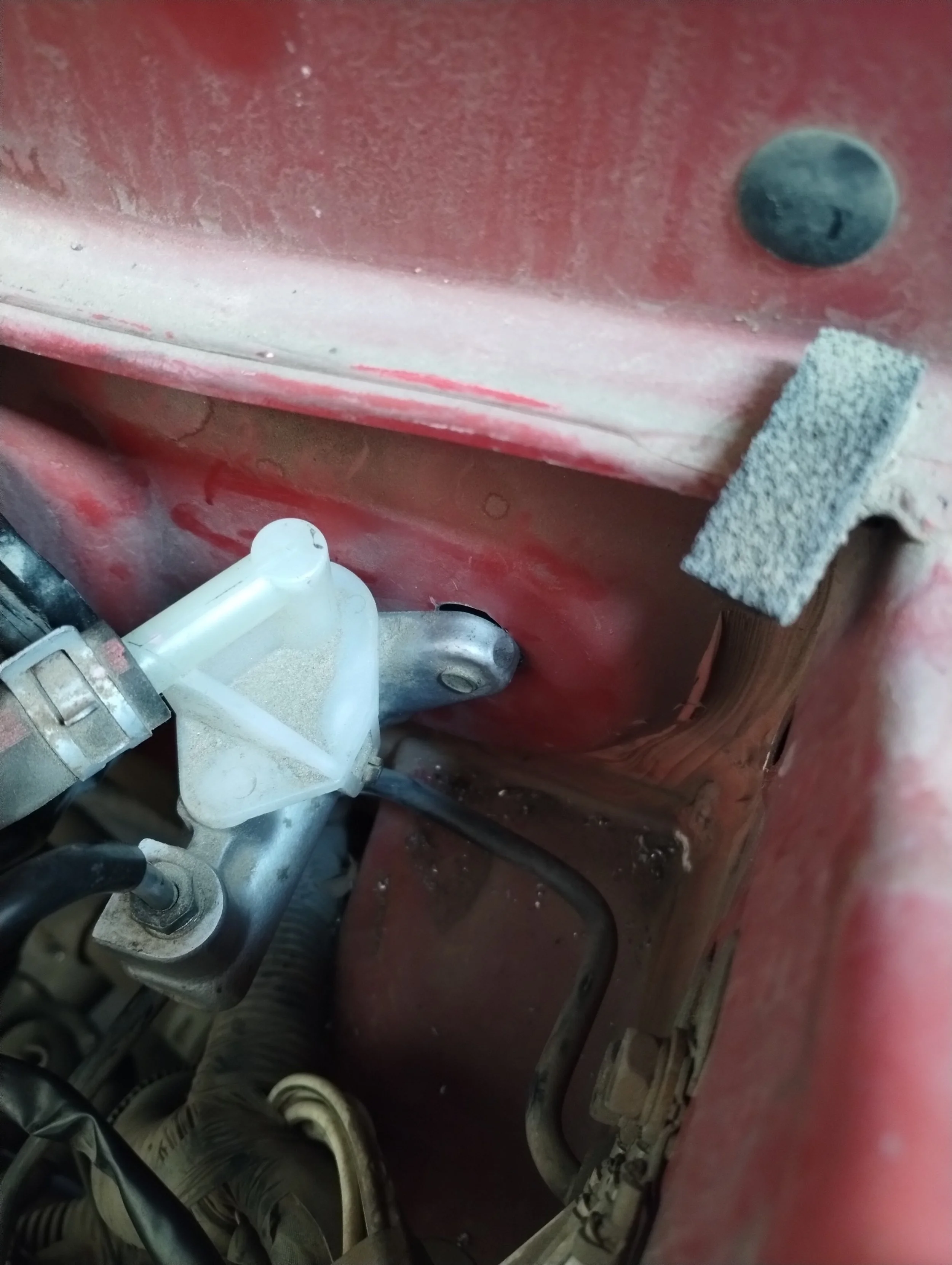
My Spyder now had a hardtop. One small issue, turns out that when removing my softtop frame, I removed one bolt hole for the hardtop strikers. Not a huge deal, I will weld a new one in place once this car is running. I could just weld the old plates back on, but I can’t find them and possibly threw them away. I have one bolt holding the strikers on for now. This car is quite a ways out from driving so this is not high priority.
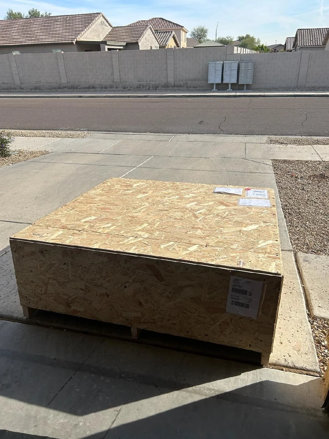
I hadn’t planned on making axles my next task. Learning from Marc and Alex, I knew there had to be some combination of axles that made this easy. Two things made axles my next project. One, I was reminded Marc came up with two different axle solutions used with the EB60 in this swap. The first of the two uses a combination of 2nd generation RAV4 axles, the second uses a combination of 2nd and 3rd generation RAV4 axles. After being reminded the first solution existed, I remembered the tC1 and 2WD RAV4.2 use the same right side axle. I knew that the tC1 axle worked on the 2AR/E350 combination with the tC1’s carrier bracket. Additionally, the E350 and EB60 use the same inner splines, and the differential is roughly the same size. That means that Marc’s first axle solution most likely works for this swap. I was 100% certain about the right side, and about 90% certain about the left. The second event that brought this to high priority was The Great Advance Auto Liquidation of 2024. Almost if not all Advance Auto stores on the west coast were closing, and their whole inventory was 70-90% off. I went and picked up the right axles for $12 a piece.
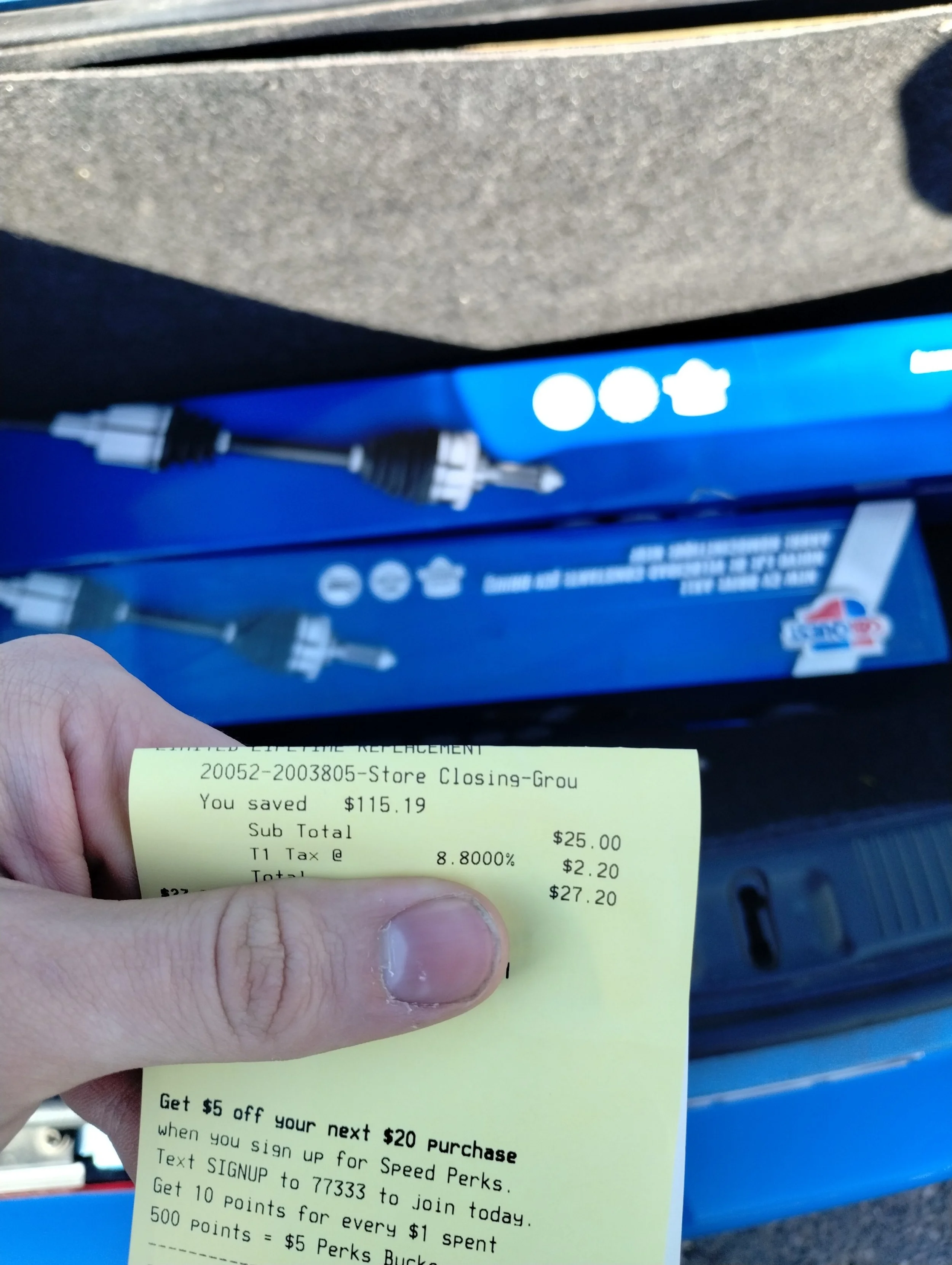
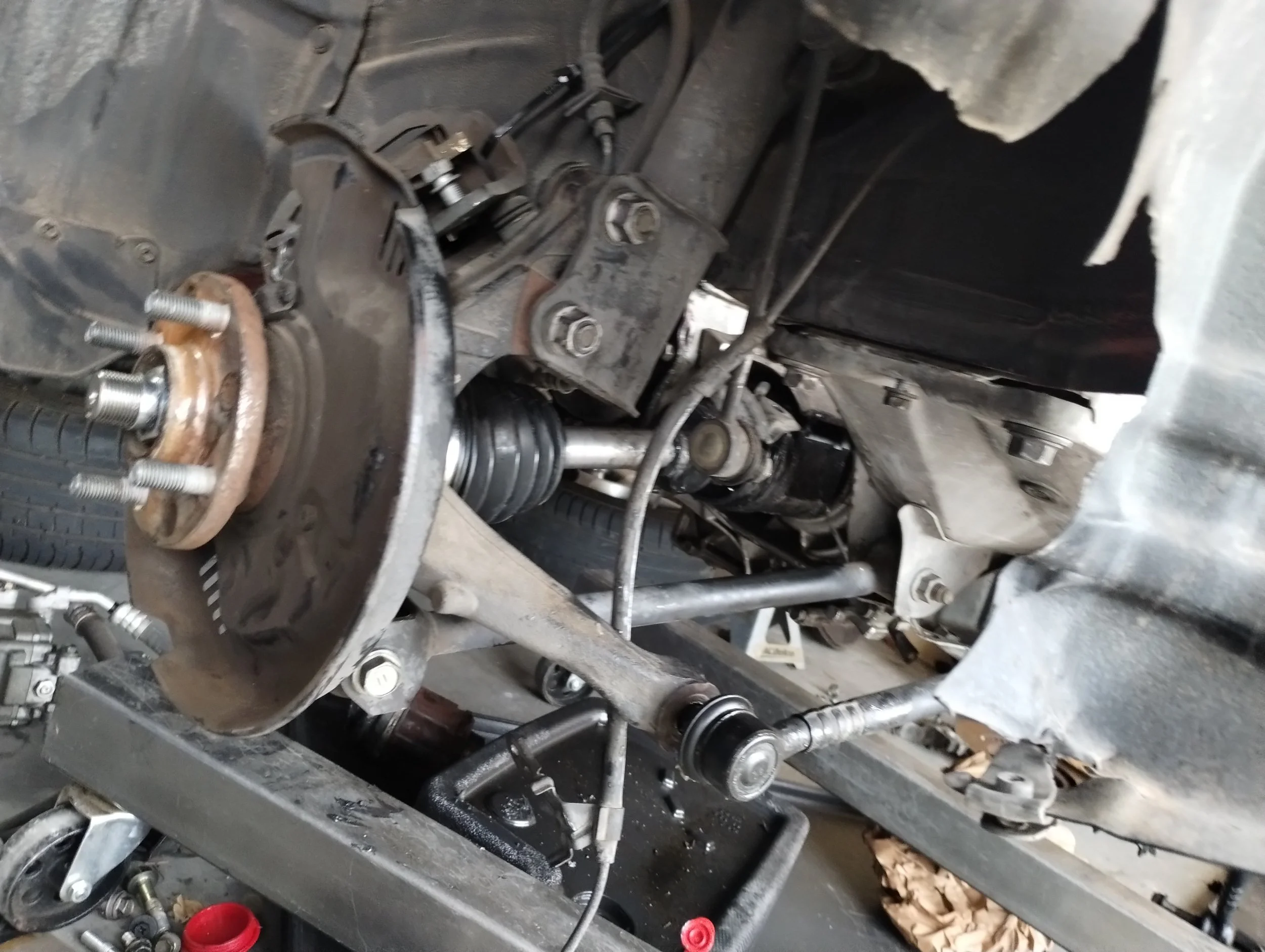
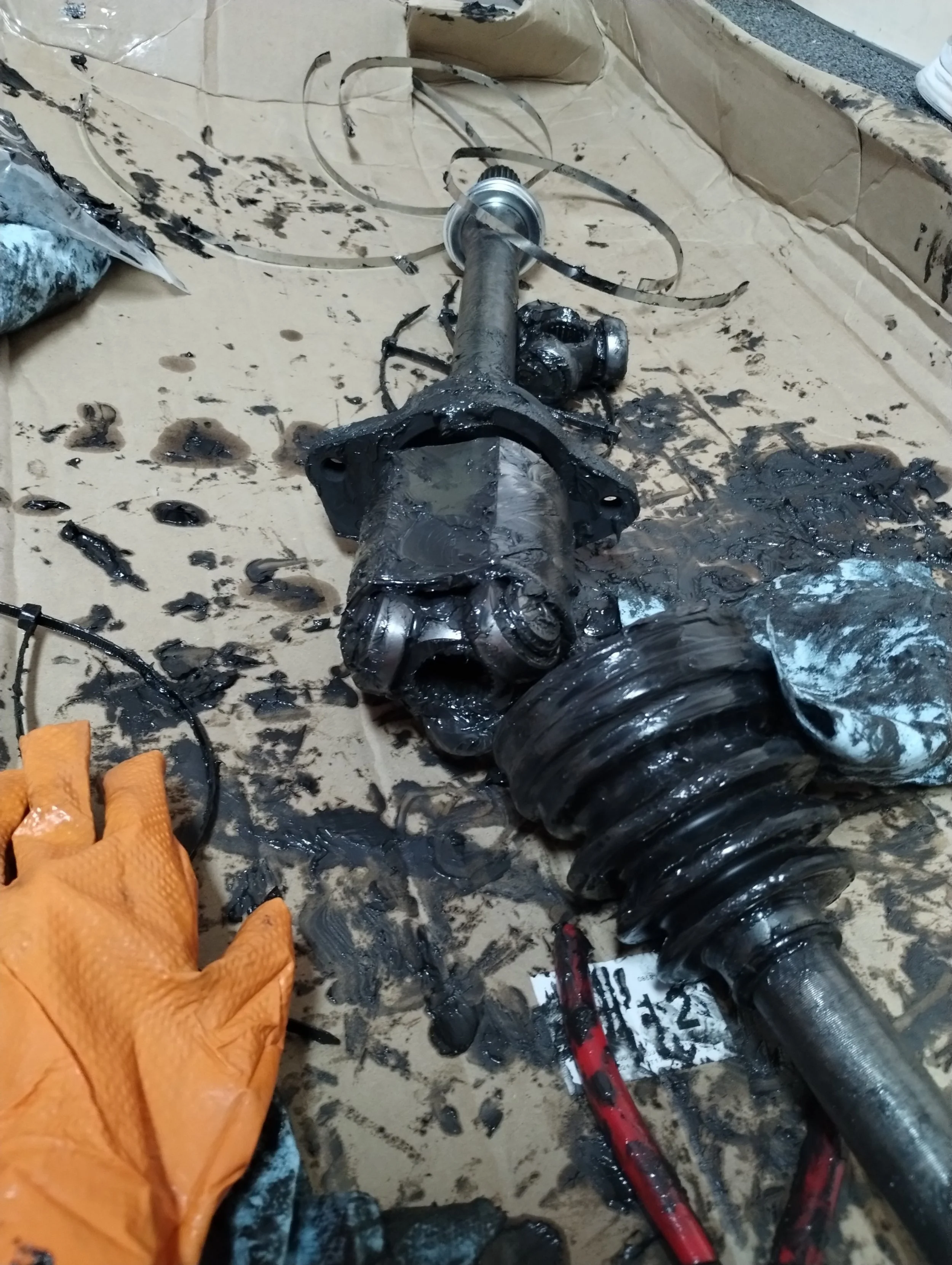
Good news and bad news. The good news is the left side combo worked perfectly. The bad news is the right side had different sizes of tulips, and the spline was different, such that I couldn’t combine those to make the axle. Marc had originally used OEM/reman axles for this, so it was a small gamble if the Advance axles would work. Either way, the lengths seem to work, so I went to find OEM parts. I already had an OEM right side tC1 axle, so I just needed to find the left side from both a 2WD and AWD RAV4.2. These cars are relatively common so these are easy enough to find.
I needed new boots, but the depth and engagement was about perfect. Being used, these are already broken in, which means I shouldn't have to worry about heat buildup causing premature failure.
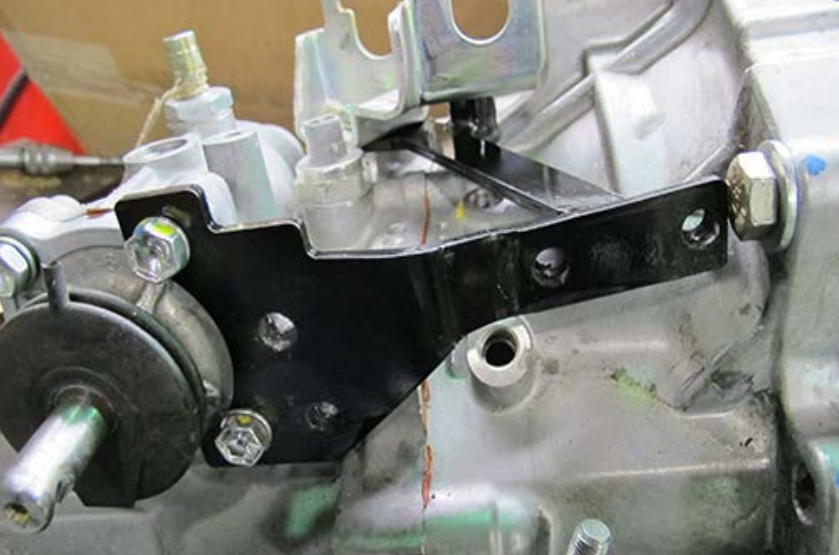
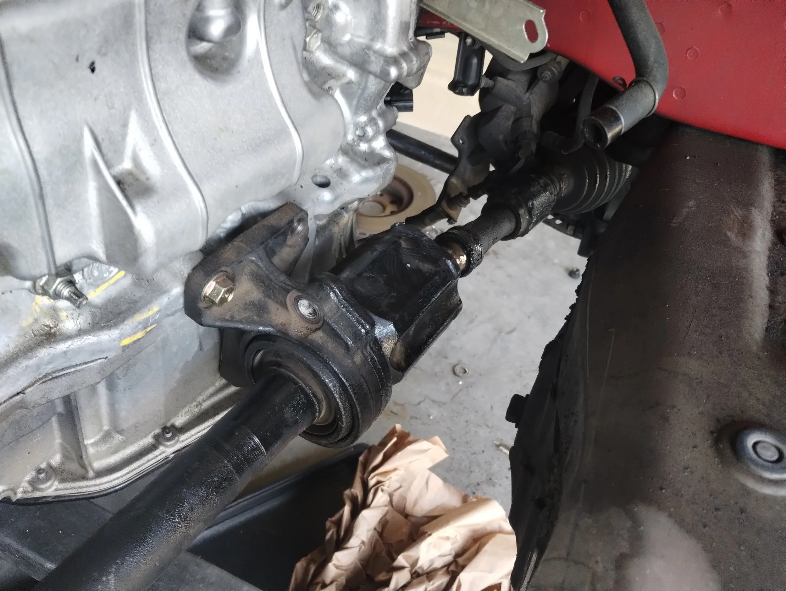
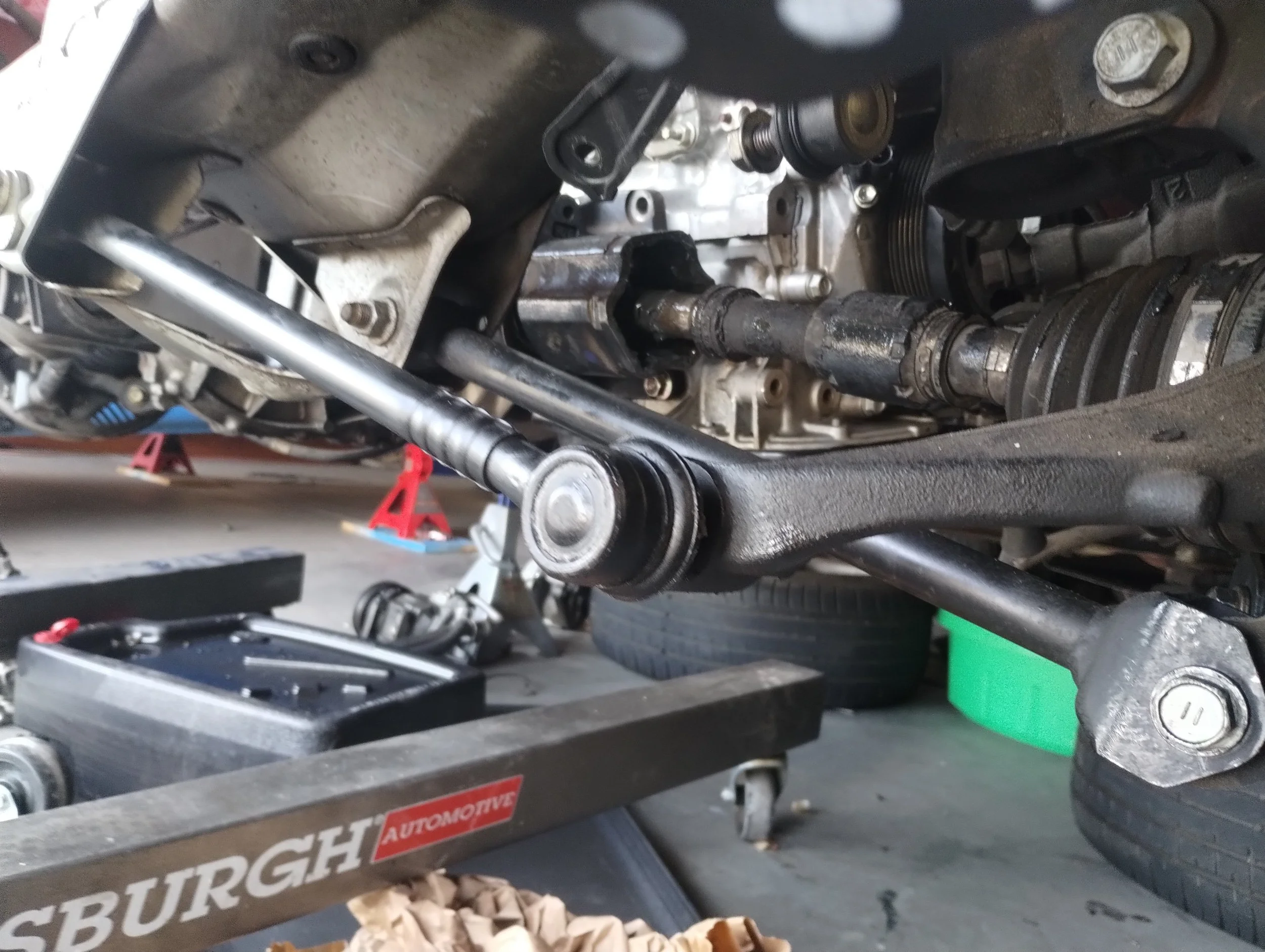
I found manual shift parts from an MR2 Spyder (Thanks Nate), and I decided to adapt that linkage to this transmission. I had to build about half of it outside of the car. Luckily, I still had my C65M around, so I was able to get the correct relative measurements for the different brackets and linkage. I made some 3D prints to test everything out to make sure it works.
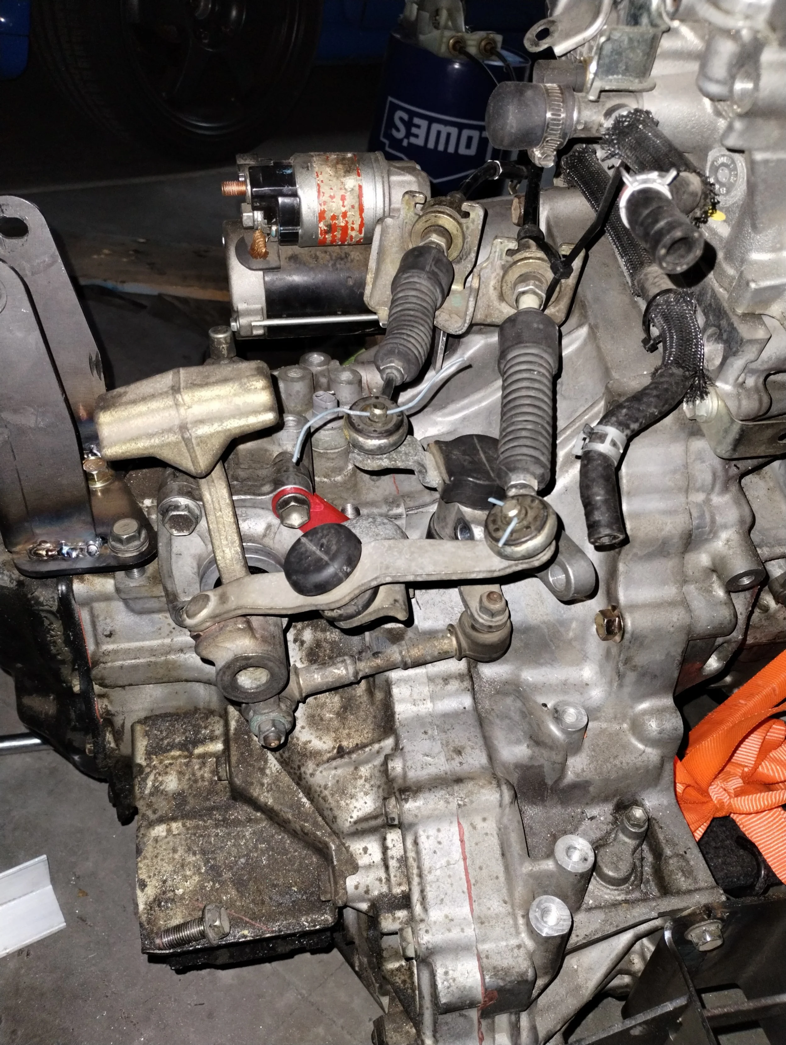
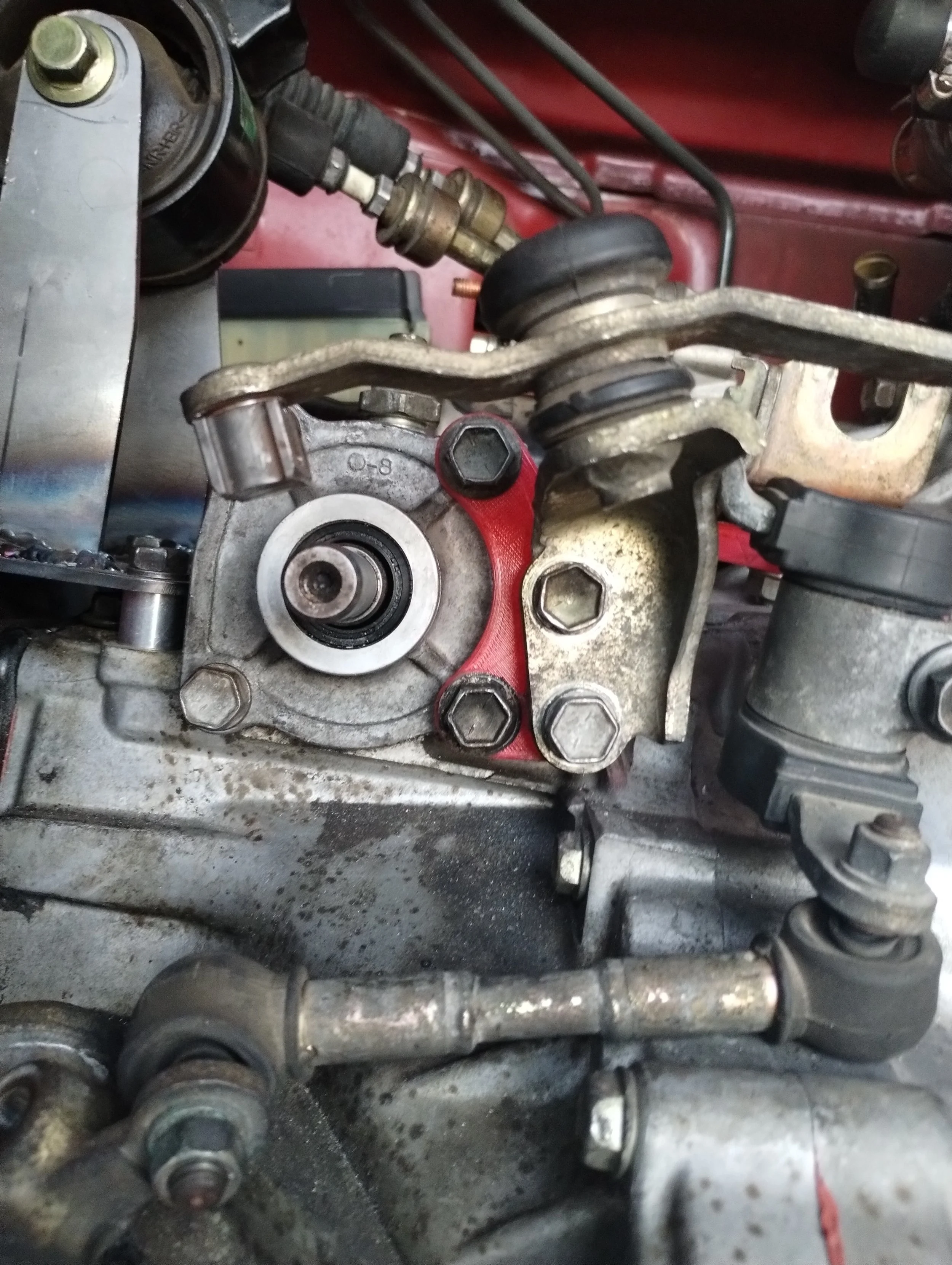
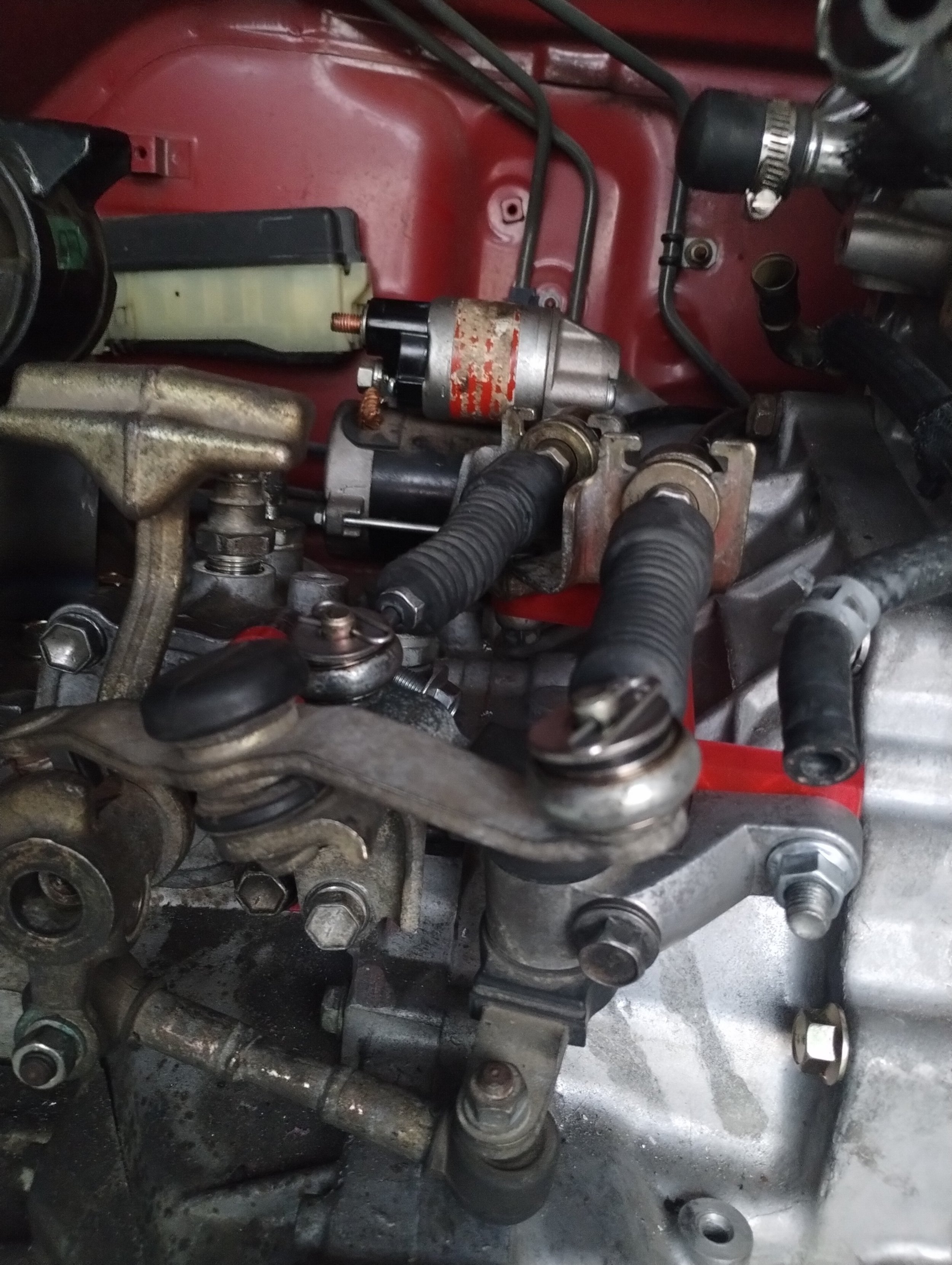
As expected, this took me way longer than expected. After I was happy with finalized designs, I got the L/R bellcrank adapter CNC machined by Marc at Frankenstein Motorworks, and the F/B bellcrank adapter made at Send Cut Send. I didn’t have a complete CAD model for the shift retainer bracket, so I welded some brackets on-the-fly. I got everything lined up just right where there were no clearance issues.
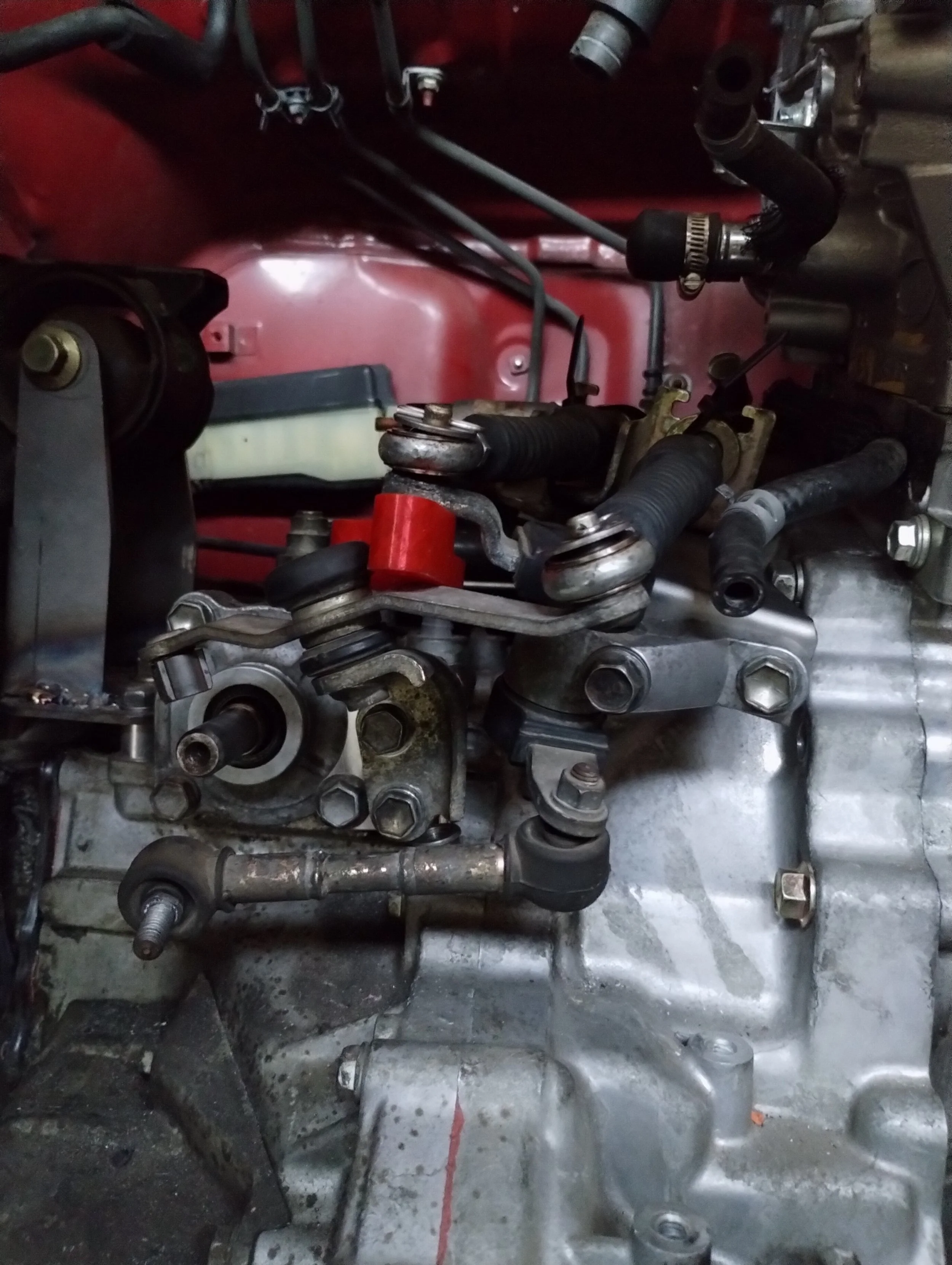
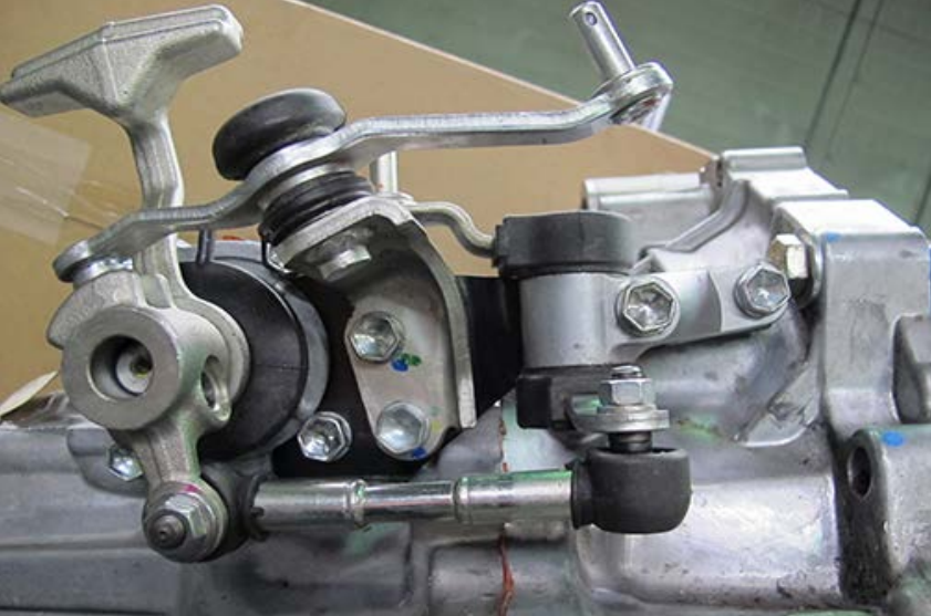
Here’s a video showing the action of the linkage. Due to of the angle of the L/R bellcrank, I had to make a new tie rod and add washers between that and the shift rod. This is essentially correcting cosine error.
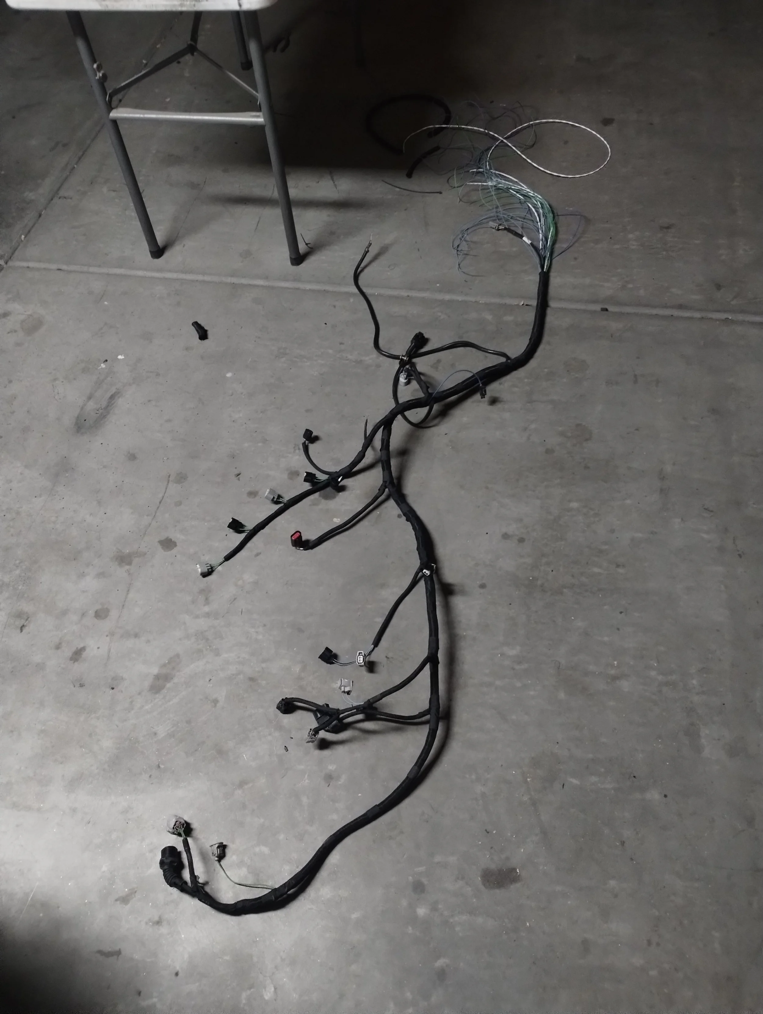
At this point, the “E350 Spyder” swap is complete. The rest can be replicated as Marc intends. As of writing this, Erik Seastead has a copy of this setup in his car, and we’ve been working on some minor bugfixes together. Next on my list was a wiring harness. I wanted to make my own instead of modifying a factory harness, and I decided to somewhat copy Max. I used the same basic topology and layout as his 2AR SW20, but I wanted something slightly wiretucked.
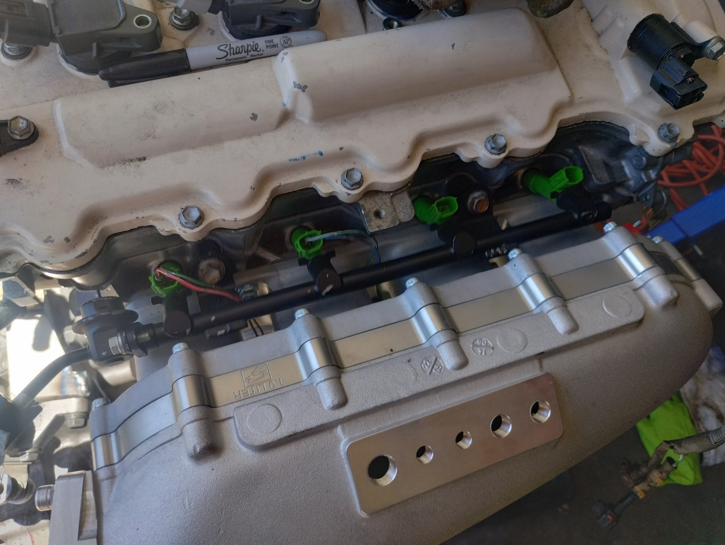
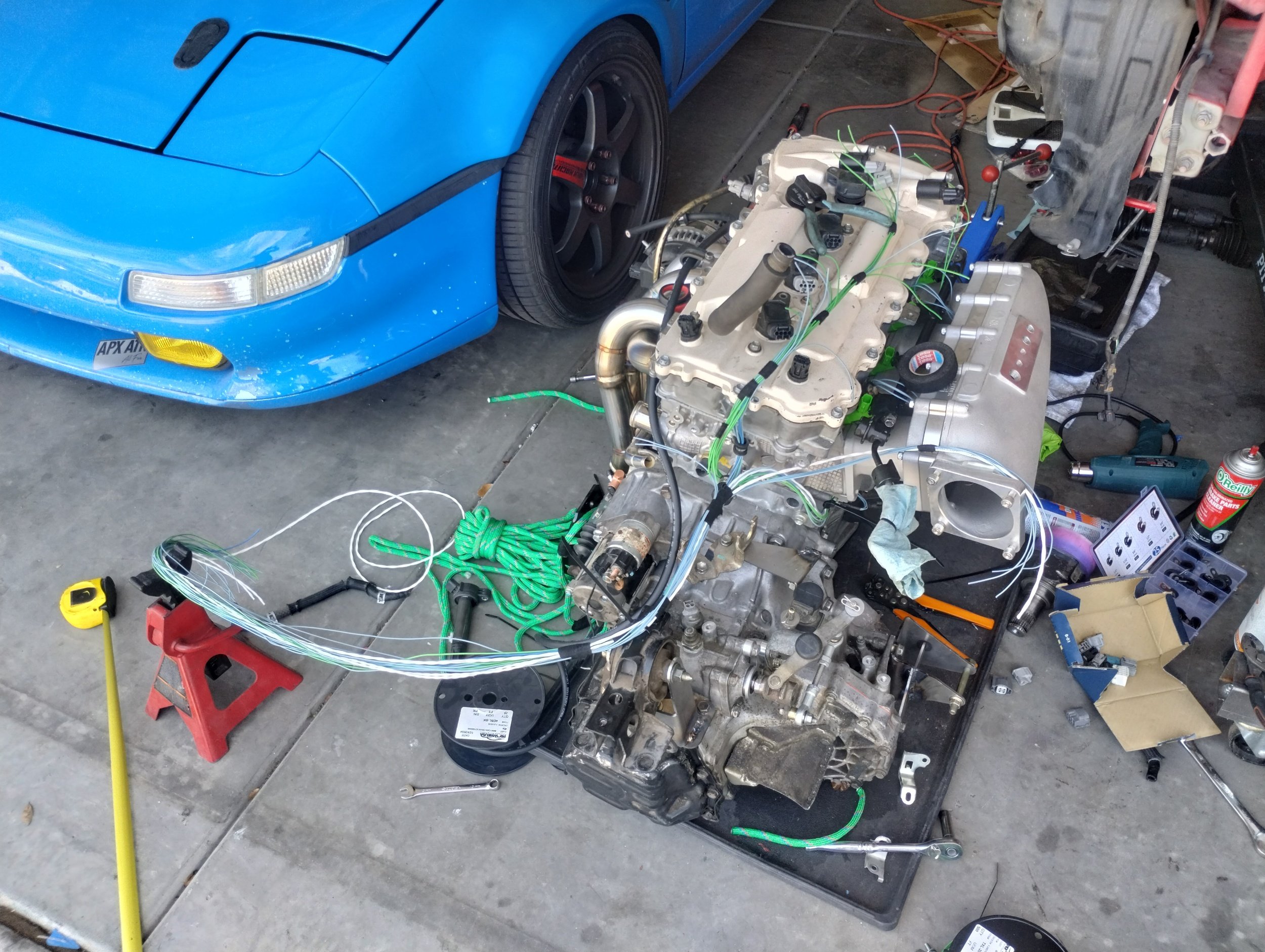
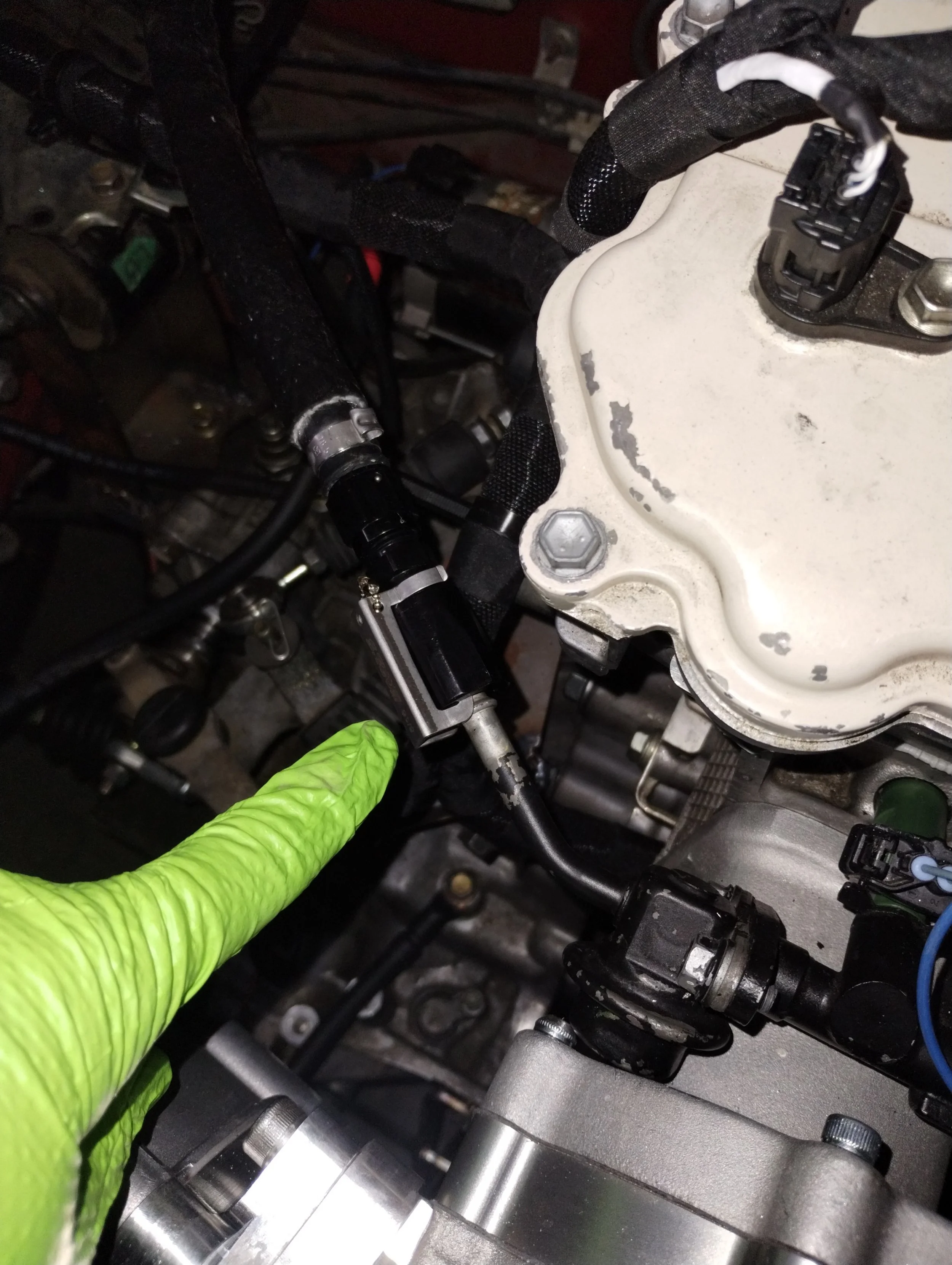
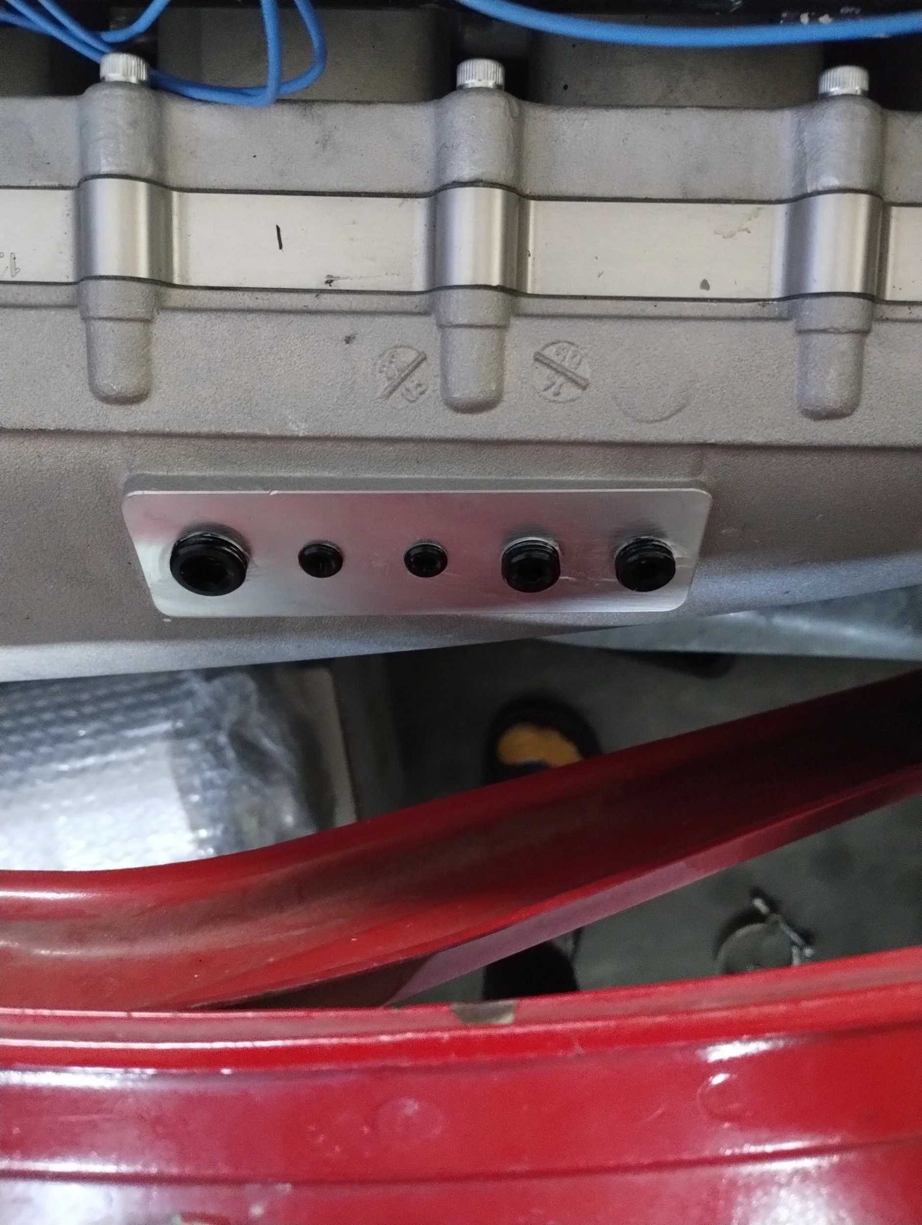
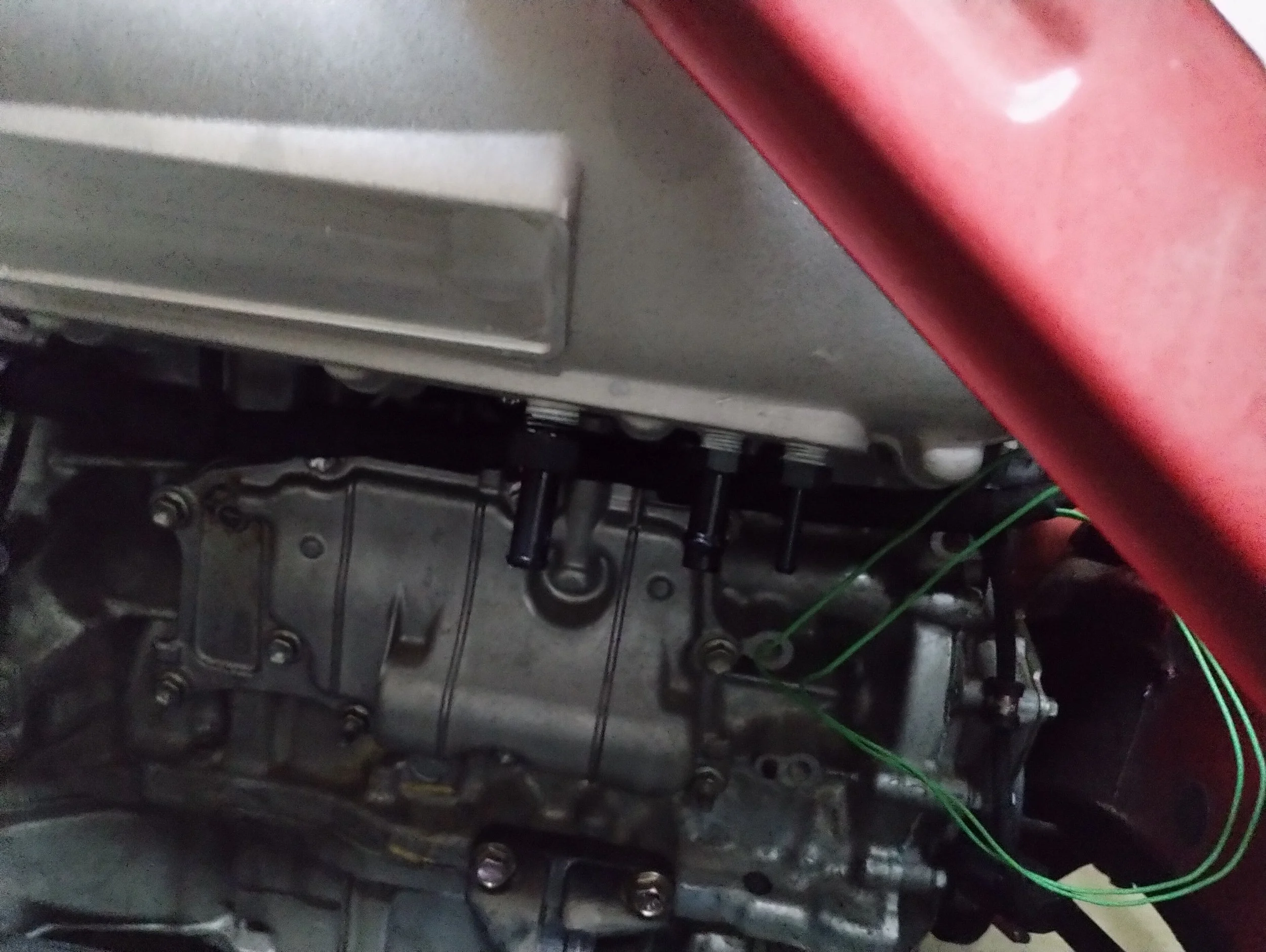
I have always wanted to do a 2AR harness where the fuel injector connectors come up from between the runners. That alone would hide 8 wires. I can run the alternator wires, knock sensor, crank sensor, and AC compressor output underneath the plenum, to keep it out of the way. I did the majority of this outside of the car, keeping an excess of wires that would run to the cabin. I’d terminate it once everything was installed in the car. I had it all mocked up, but was waiting on terminals and some connectors before finalizing it.
Next on my list was engine internals. To decrease the scope of this build, and to accelerate the functionality, I got in on the preorder of FMW “Street” cams. These do not require changing the valve springs. The soon-to-be-released “Track” cams do, the higher lift would induce coil bind. I plan to switch to the “Track” cams when available, so I replaced the springs while I had it apart. Hot Rodder’s Fallacy, anyone? Having just recently did this on the 2gr in my SW20, I was comfortable doing this with an air compressor and the Toyotool ValveMaster. This is not sponsored product placement. It seems like these might not be available anymore.
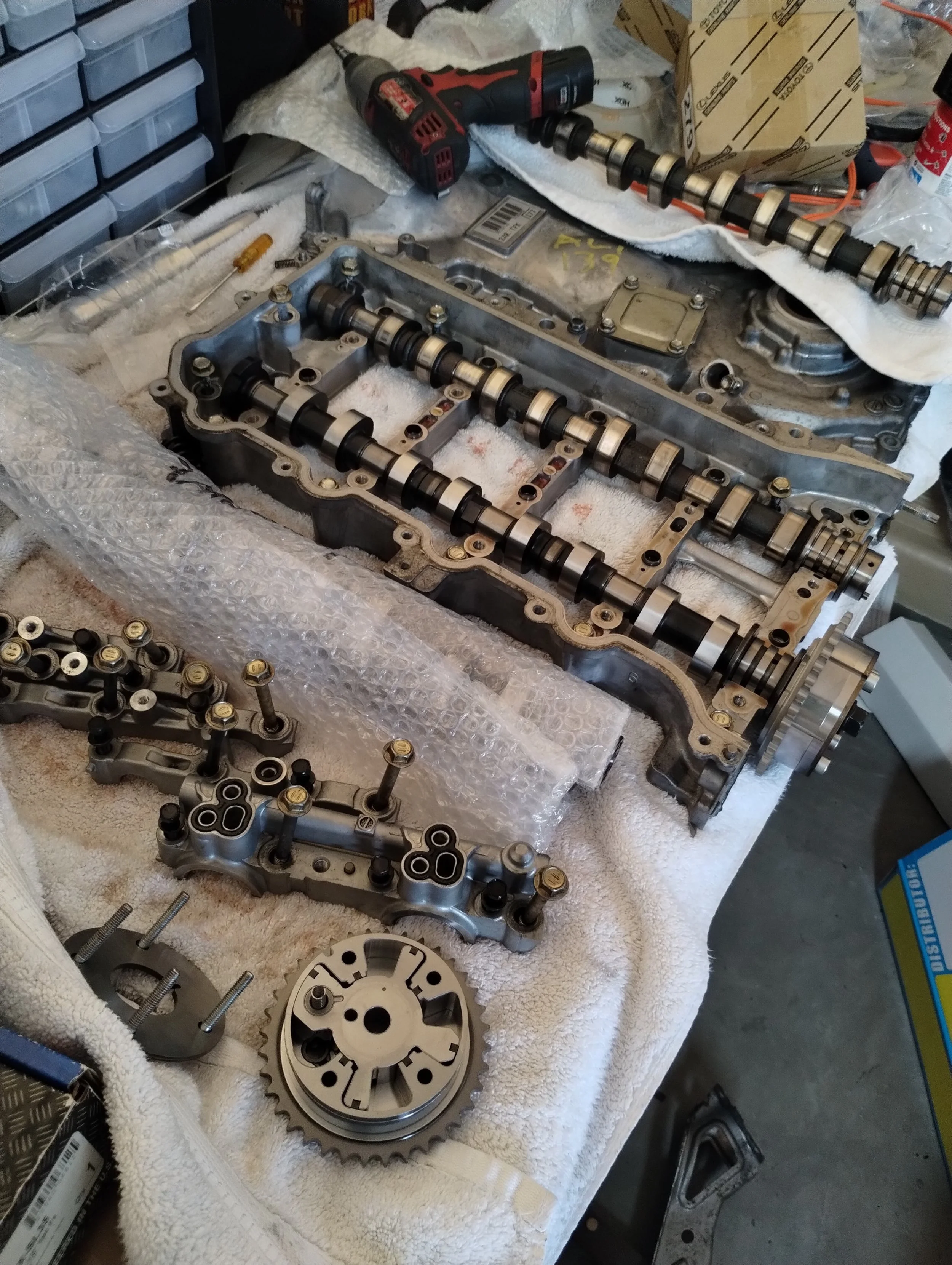
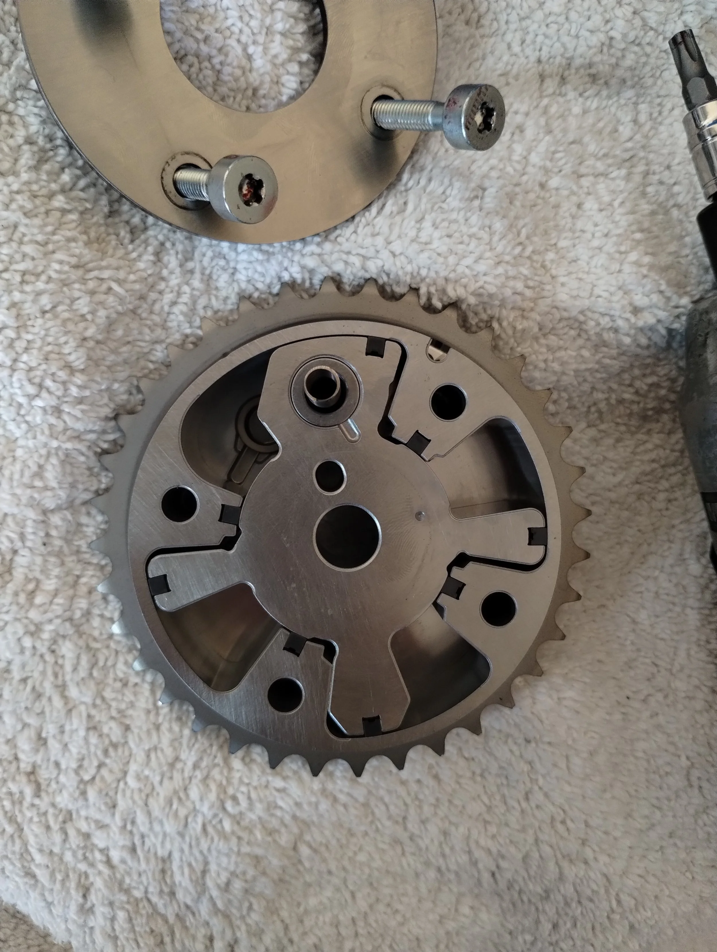
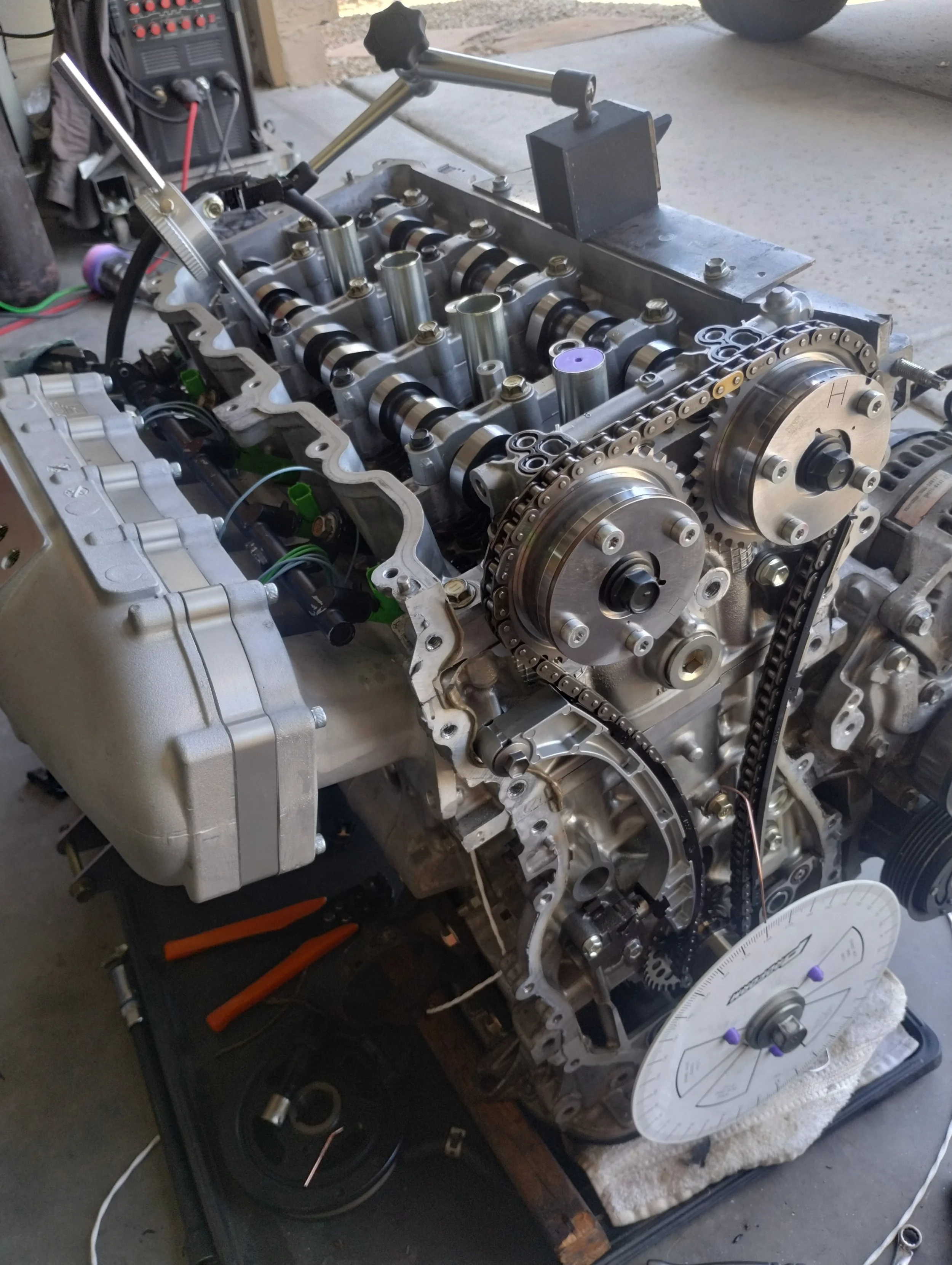
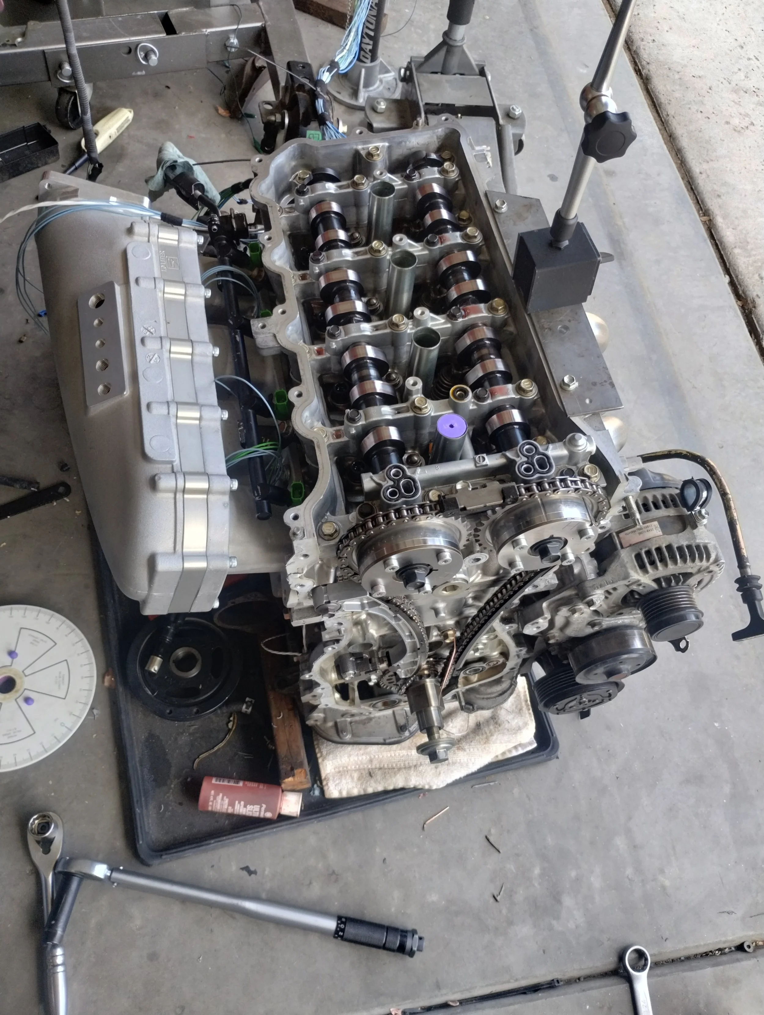
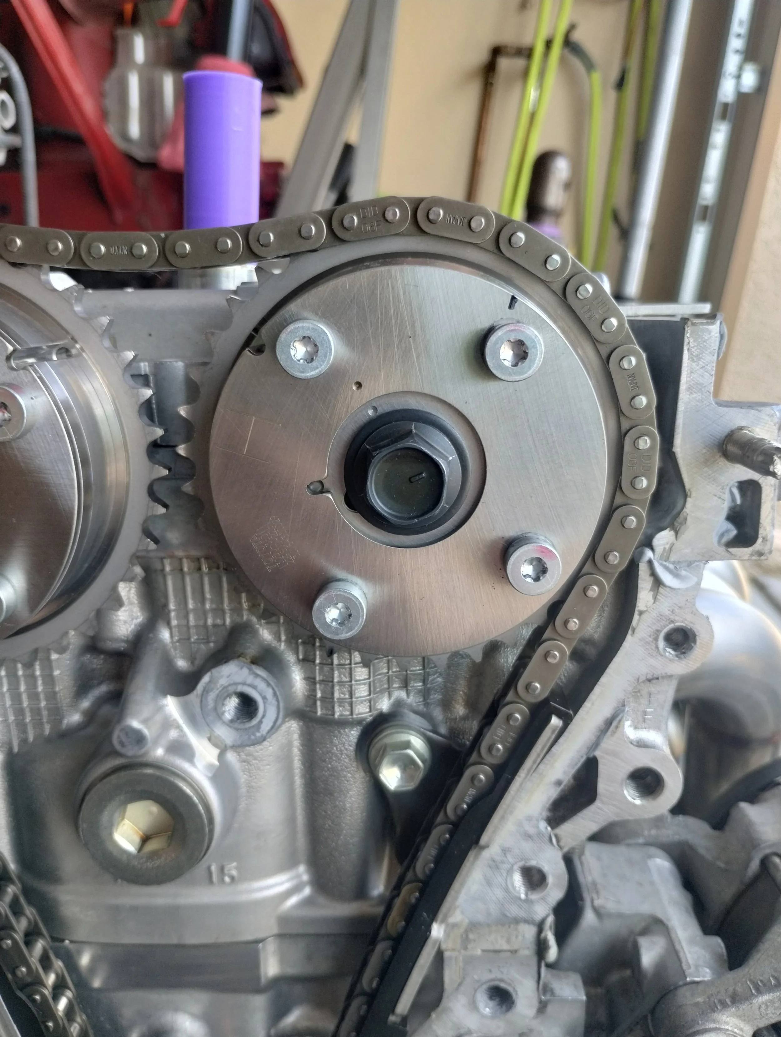
To compliment my new camshafts, I opted for a brand new pair of 60 degree cam phasers. While I’m not sure if I’ll need this much range, it won’t hurt to have. I installed two intake phasers, as 2ARs are somewhat known to lose exhaust cam control at higher RPM (citation needed). I think this is due to the direction the phaser moves relative to the direction the timing chain is moving, but that’s just speculation. I took the phasers apart and installed lock pin springs from FMW. This is not something he has normally lists on his site, but it increases the preload on the lock pin, which should prevent any VVT-i startup rattle that 2ARs are known for.
Next on the list was checking cam timing and valve clearance. Since I’m not using a factory exhaust phaser, and I’m using an aftermarket ECU, I will not be using any of the factory timing marks. This just means I have to use a degree wheel and dial indicator to check my valve clearance and set timing. In order to do this, I needed to make one solid lash adjuster at the right height to make sure I have enough valve clearance.
I have a spare 2GR sitting around that I have taken many parts from. Marc told me that 2GRs and 2ARs use the same adjusters, which turned out to not be true here, my 2GR adjusters were slightly shorter than what came out of my 2AR. Either they differ, or they differ between design revisions. One small tack weld was all that was needed to prevent the adjuster from collapsing. I also welded a bit on the bottom to make up for the height difference. Again, this is not to be run in the motor, this is just to create a solid fulcrum to lift the valve against.
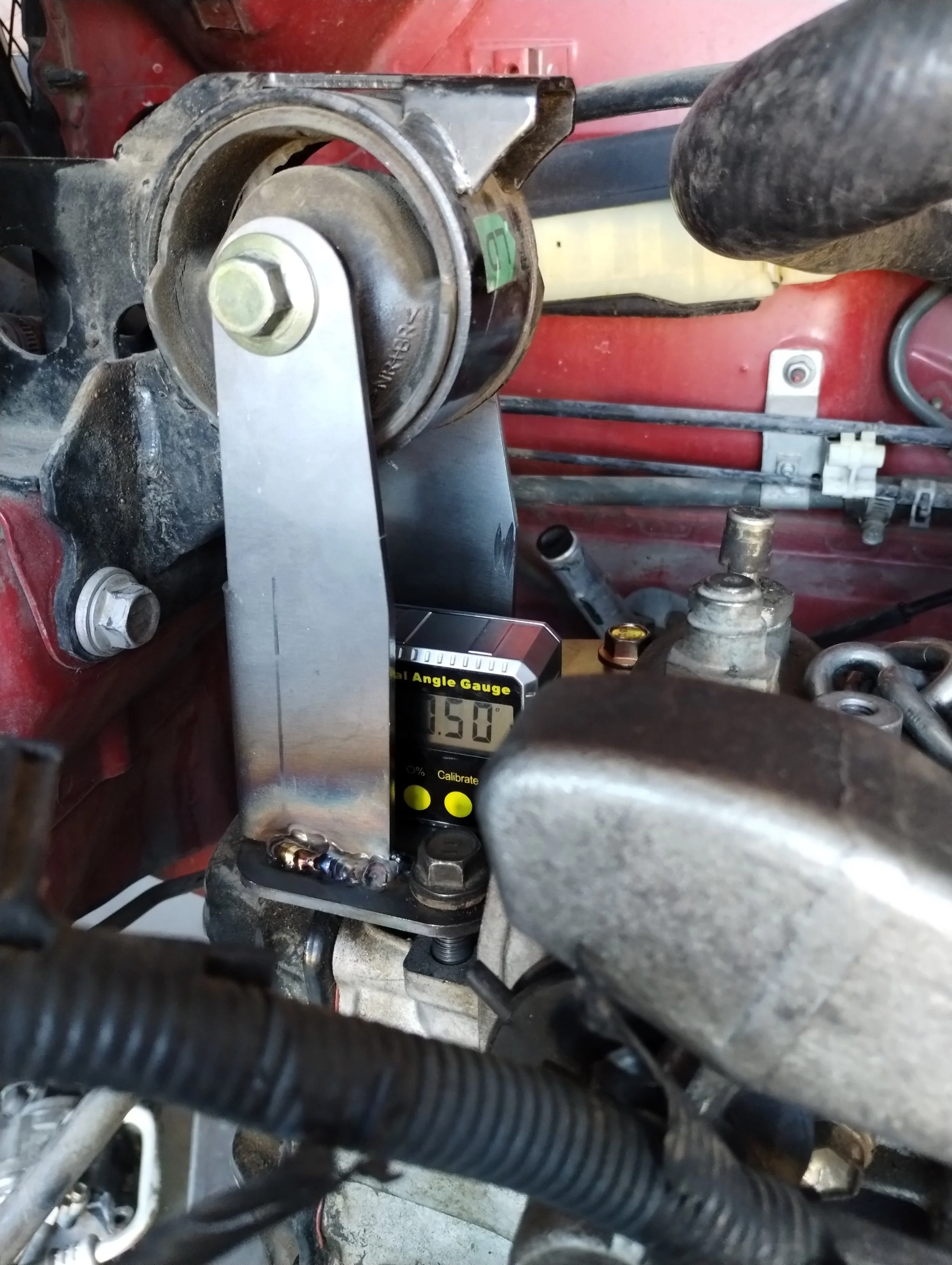
Being a VVT-i motor, I need to check clearance at all valve angles. I would never run a motor that can make piston contact with a tuning error, even if I’d never actually use that range in the real world. These are “60 degree” phasers, meaning the cam timing can change up to 60 degrees of crankshaft rotation, or 30 degrees at the cam. These phasers have 36 teeth, which means I can simply advance the phaser 3 teeth from my actual starting position, instead of going through the effort of unlocking the phasers and moving the cam manually.
This was one of those projects that I had to redo 15 times to fully process. I was hopeful that I could advance the intake cam more aggressively by half of a tooth, but unfortunately piston clearance didn’t allow for that. These FMW cams allow timing changes by a half-tooth, by having two dowel pin locations 165° apart. I ended up running the intake cam at the factory timing mark, and I’m not sure how to describe where the exhaust is. YMMV, this is not gospel, check all the clearances yourself. I ended up with the following centerlines:
Exhaust cam: 68 degrees btdc at home, 128 btdc max advance.
Intake cam: 134 atdc at home, 74 atdc max advance.
Note that the exhaust cam centerlines will be backwards compared to a factory exhaust phaser. In this case, my exhaust cam at rest is in the minimum clearance position, and my intake cam at full advance is in the minimum clearance position, due to running two intake phasers. Marc has a set of instructions on how to time one of these without timing marks on Discord. They do a much better job than I would be able to here.
With my FMW intake setup and skunk2 plenum, I was still hellbent on running an electronic throttle body. Skunk2 lists the throttle body as a “Ford 5.0 pattern”. I was unsure if that meant Foxbody 302/5.0 or Coyote, so I reached out for clarification. Skunk2 support said it was a Coyote. After purchasing a gen3 Coyote throttle body, I confirmed that is not correct.
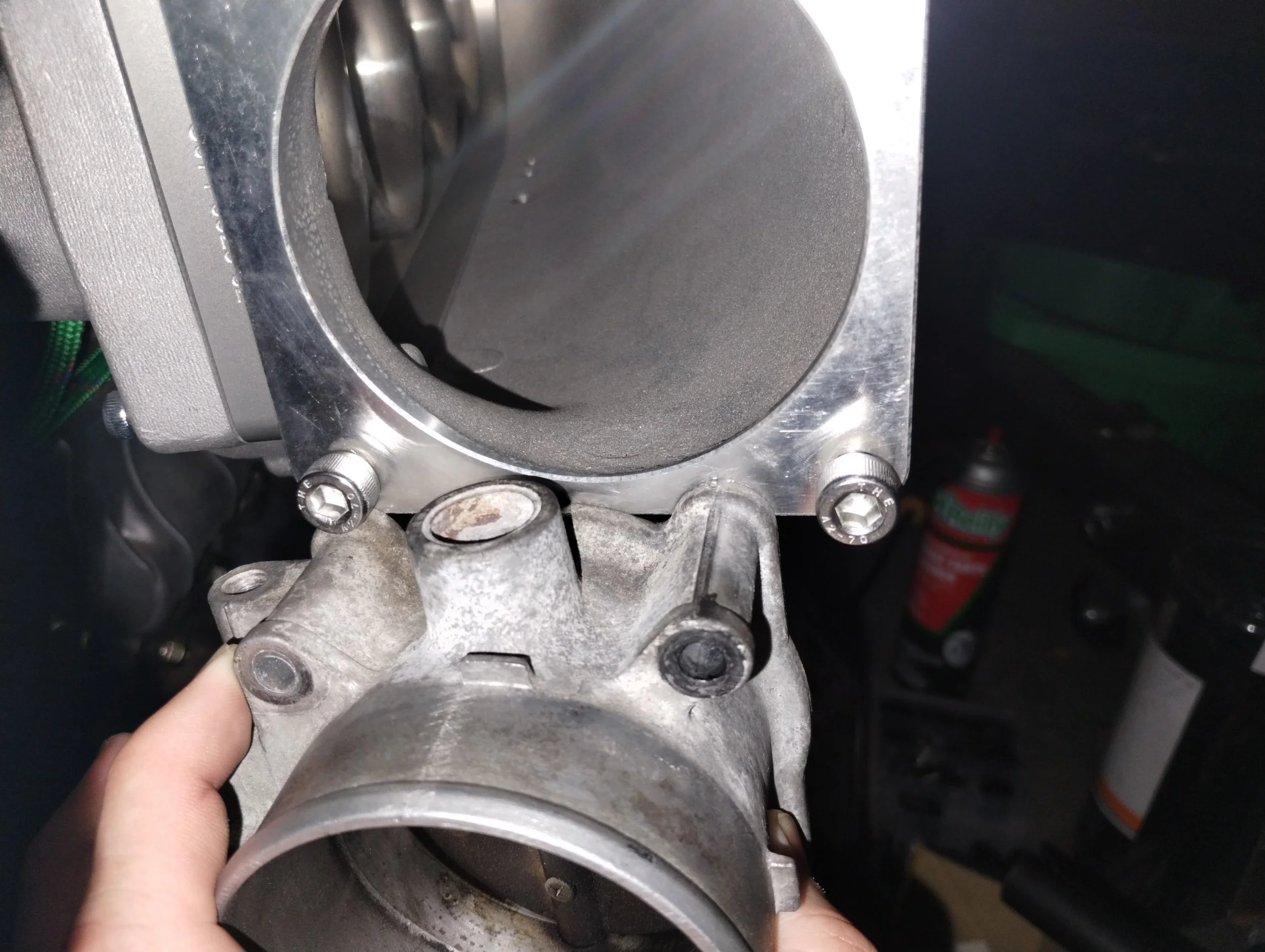
Not even close
I went back and asked if it was supposed to be an earlier Coyote, and they simply replied with dimensions instead of elaborating. They would not recommend me any throttle body which will attach to this plenum. After some research I’m fairly sure that this is a Foxbody pattern. Since Skunk2 is incapable of assisting here, I had to make an adapter to some other throttle body. I decided to keep this Mustang throttle. There seem to be a few variants based on year and trim level, but the throttle body I got has an 80mm butterfly— a bit smaller than the 90mm opening of the Skunk2 plenum, but more than enough for the amount of power I was looking for. After a few minor revisions I ended up at the below.
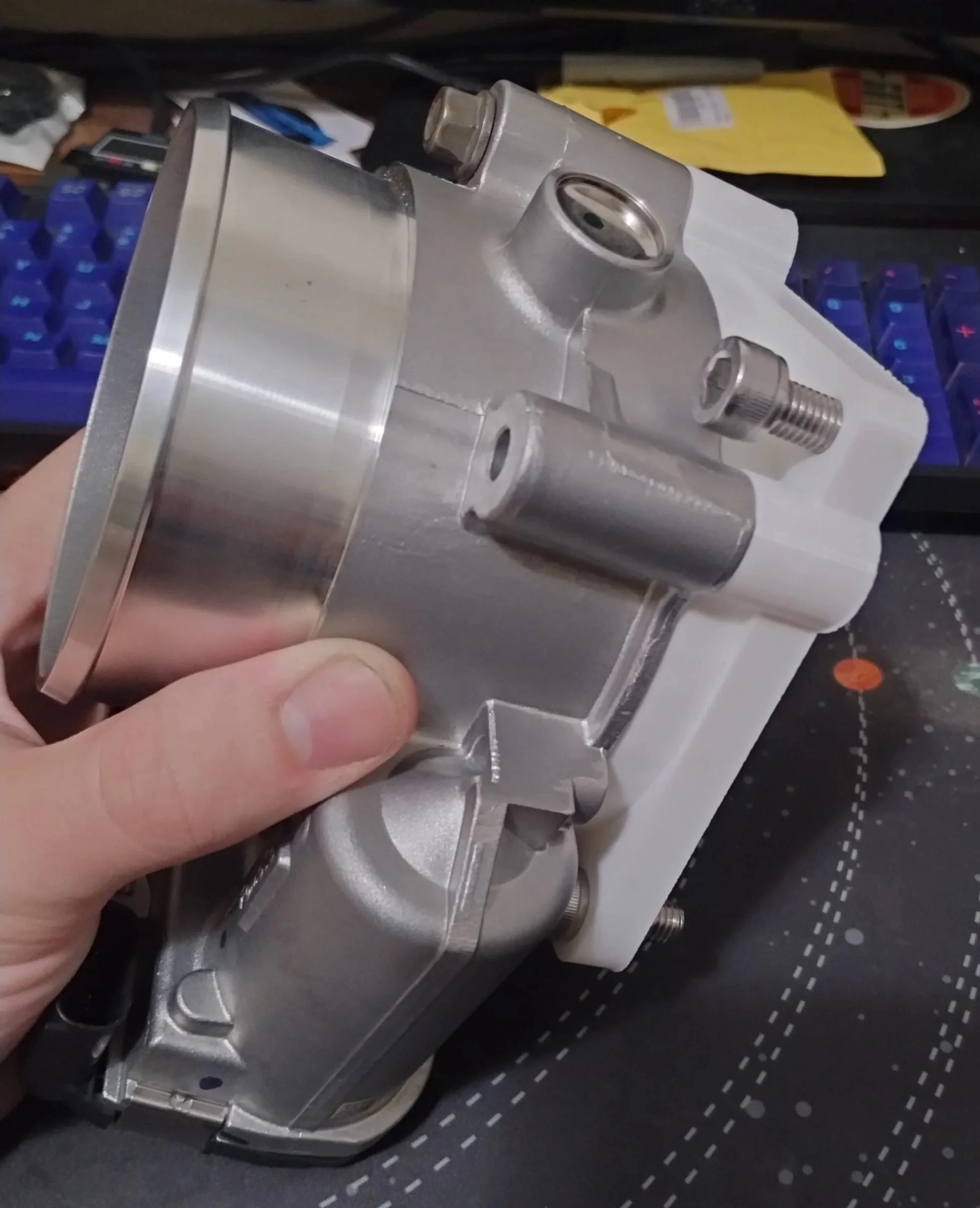
I went through a few revisions to ensure the part had smooth transitions between the throttle body and the Skunk2 plenum. Marc was again volunteered to make a few of these in aerospace grade aluminum.
The last item on the list before final engine install was to install my LSD. I originally planned on leaving the open differential in for “V1”, but I was convinced otherwise. Hot rodder’s fallacy and all that. I had recently received an order of Quaife QDF25Es so it made sense. I had planned on this anyway, to do in “V2”, but I decided I would regret not doing so. This was a good time to install a long ratio 5th gear as well, to combat the short ratio FD that I chose.
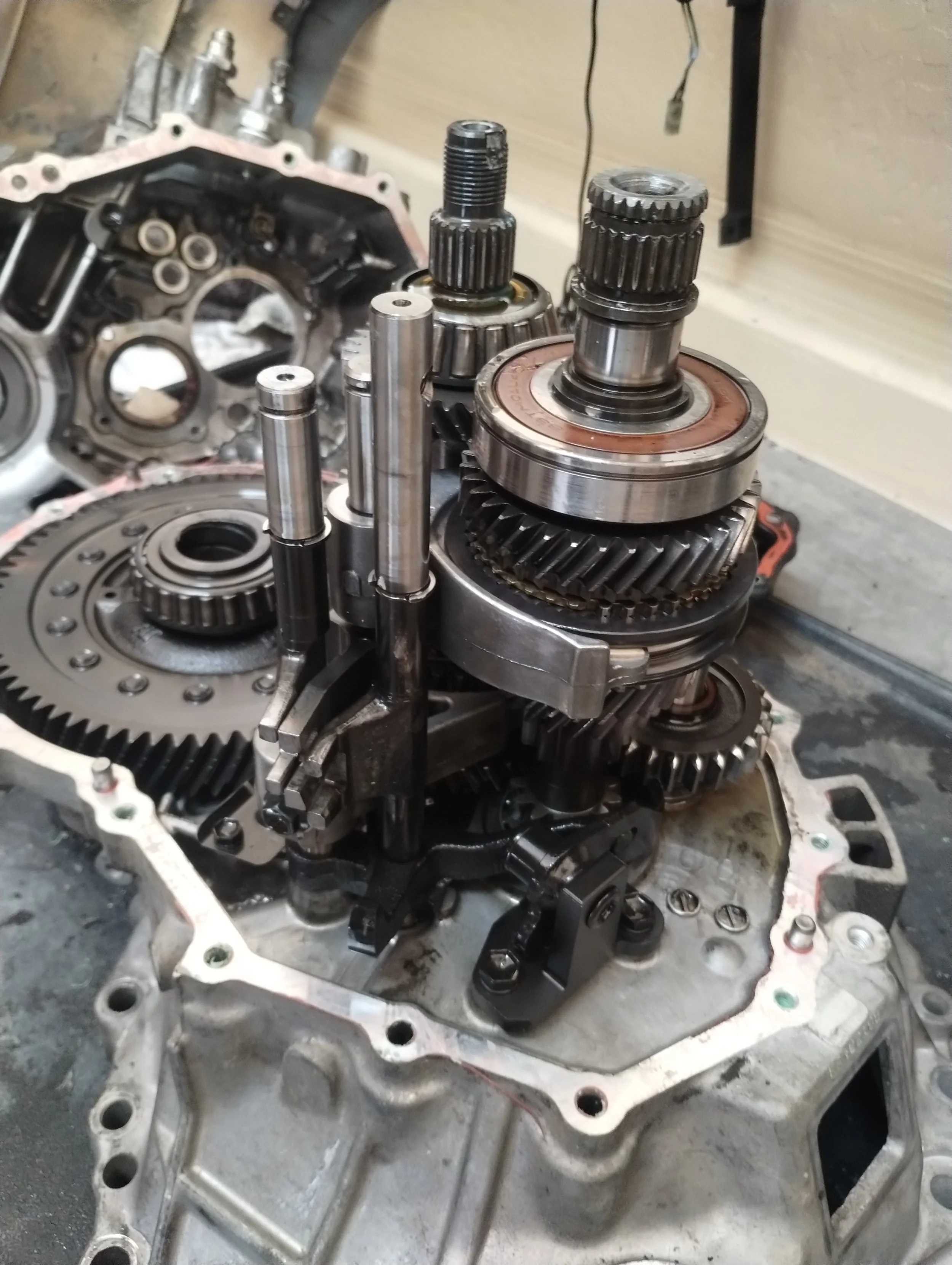
This was the single cleanest transmission I’ve ever opened up. Everything in here looked brand new. This must have been from a pretty low mileage car, or it had a transmission replacement at some point. Everything looked to be within factory specs, so I don’t think it was rebuilt. Installing the LSD from here was pretty straightforward, with one tiny caveat, this was the first time that I’ve ever had to re-shim the differential when installing a Quaife. So far, every transmission I’ve built has been in-spec when reusing factory shims. This one was just barely out of spec, something like 16 in*lb when the maximum allowed is 14. This had the thickest shim available, at 2.85mm. I ordered the sixth size down, and my preload was comfortably in spec. Reassembly is the opposite of disassembly.
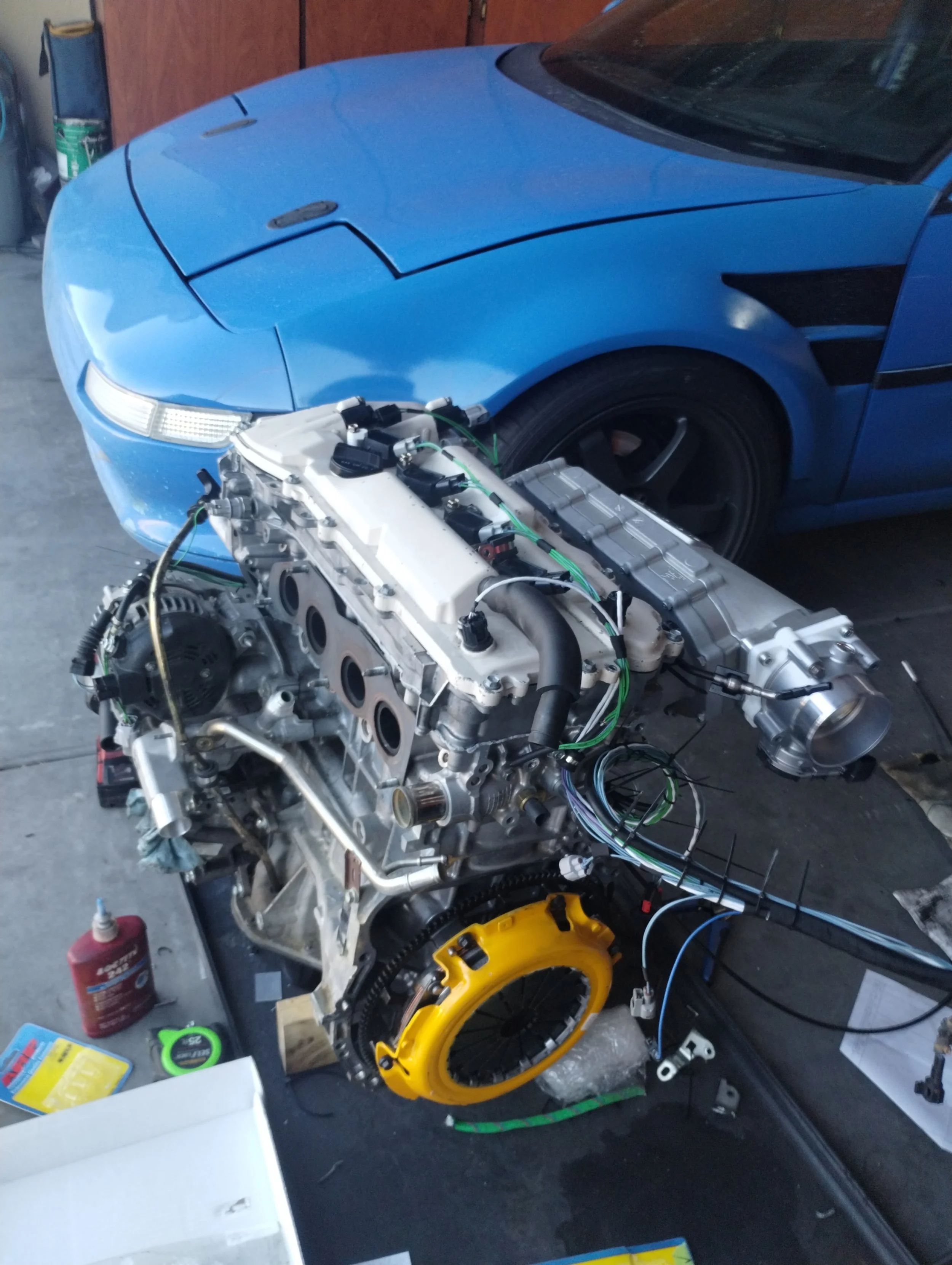
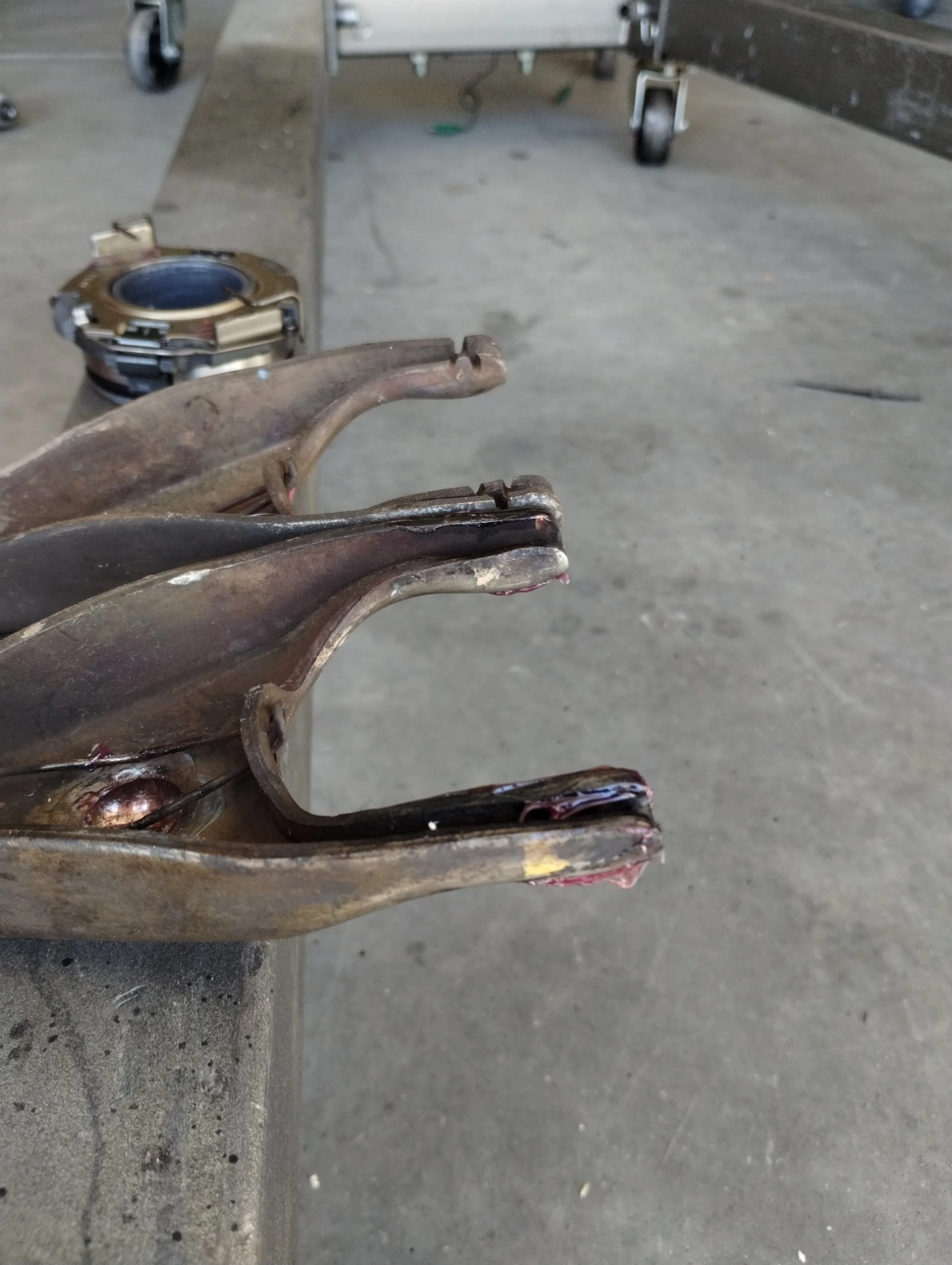
After all this, it was time for final assembly. There were a handful of last minute parts I had to source, including flywheel bolts, a clutch, a thermostat, and a few seals. Something interesting I noticed is that there are at least two styles of clutch forks. One has grooves for the throwout bearing retainer spring, and one is smooth. The spring must have changed at some point, and the bearing I have attaches to the slots, so I used that slotted fork. Next I installed the header, alternator, thermostat, and so on. I left the intake manifold off, because that one is really easy to install while the engine is mounted. I also left off the wiring harness as to not damage it.
If Max could see where his 2AR is today…
Before I could actually start the car, I needed to finalize wiring. After terminating everything at the ECU, it was time to install it in the car. There are still a few things I don’t love, and in the future I’ll probably pull everything out and redo it, but for now, it’s nice. More wiretucked than most cars, but still serviceable. Once I got the engine bay side finalized, I measured some lengths and took it indoors to terminate the ECU connections. I set up a table in my spare room and did all of my wiring indoors. No longer must I sit out in the hot garage crimping terminals all day.
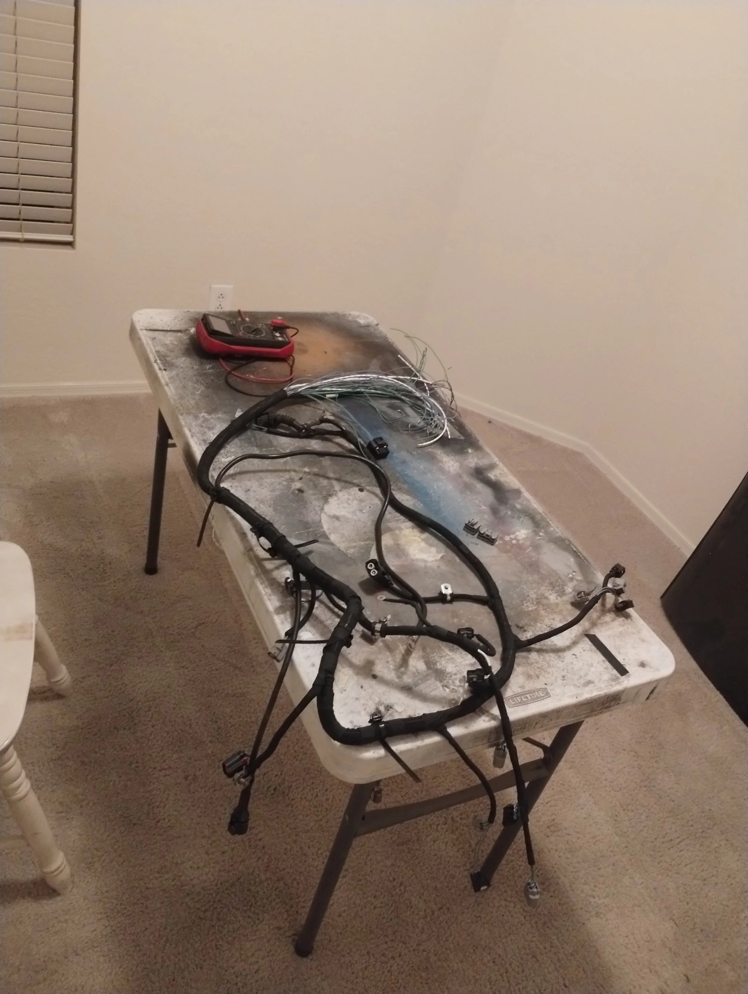
I used TechFlex F6 sheath, because this won’t be near any extreme high heat areas. I only went underneath the intake and above the transmission. There are no wires on the exhaust side of the motor. F6 has an operating temp of 257°F and a melting point of 482°F, so I think I should be fine here. If I need to come back in the future and fiberglass shield a few spots I will do so.
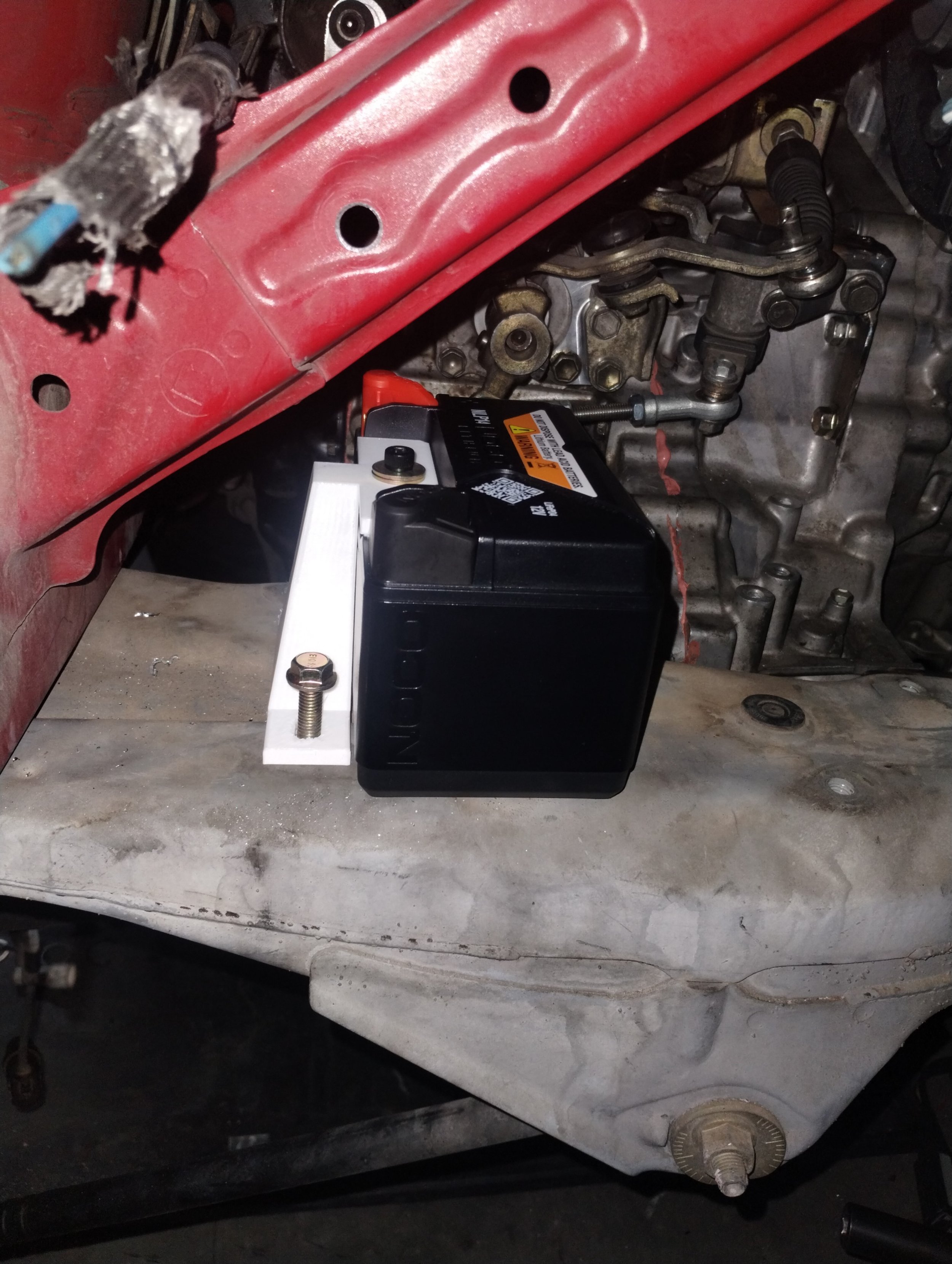
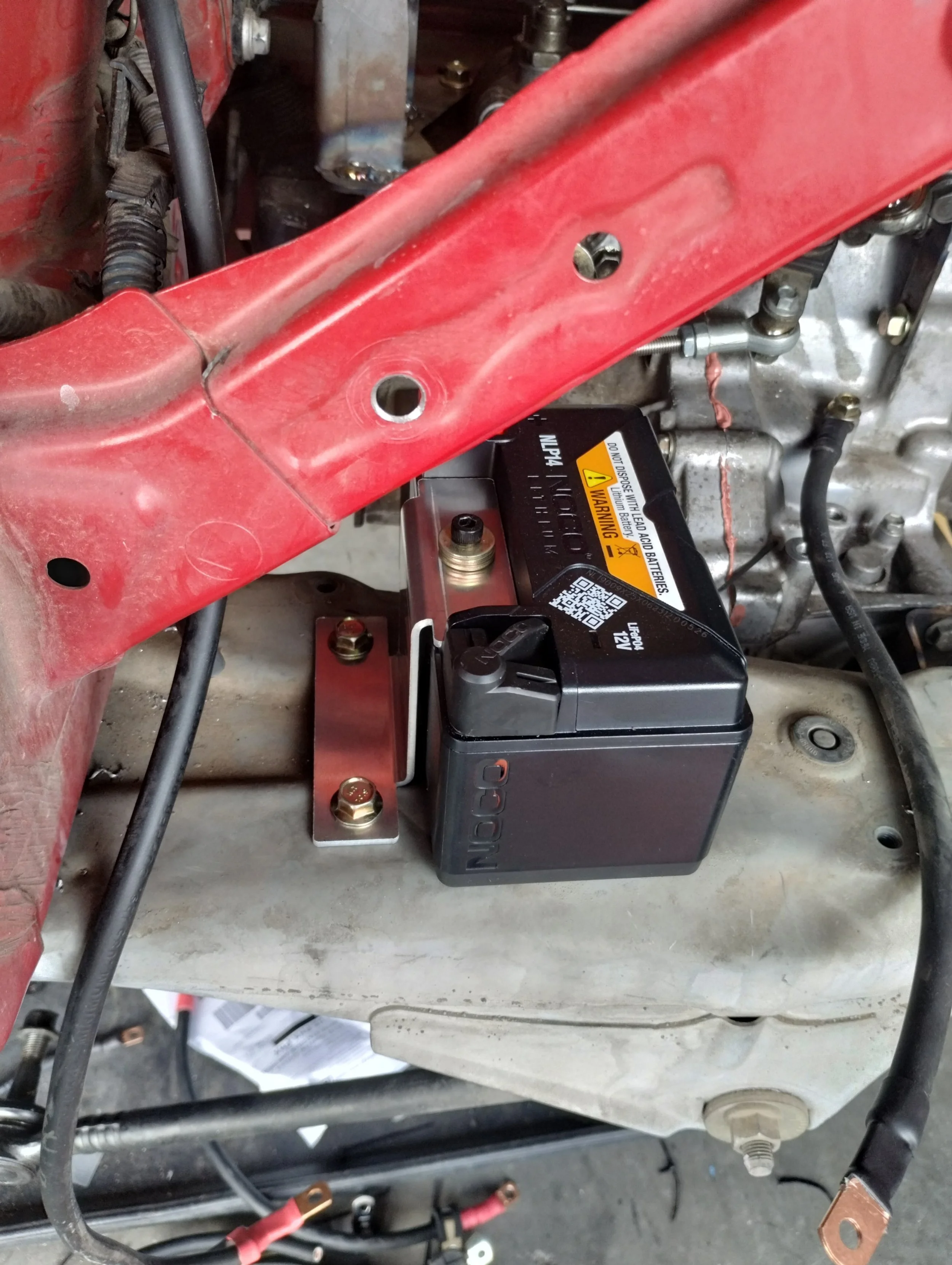
The last last thing to do was get power to the car. I chose a Noco NLP14, I’ve had good luck with this in my SW20. On this car, I mounted it to the subframe. Another quick 3D model and another SendCutSend bracket.
That was the last thing, right? Well… I was still missing a fuel line. For some reason, these 8mm quick connect fittings are a little hard to come by. Marc recommended Earl’s AT991965ERL. These were a bit expensive, which is fine, except their estimated ship date was 12/31/2026. I misread that when placing the order in November of 2025. I didn’t think twice about it. All the other parts got delivered; fuel hose, heat sleeve, the works. I called around and found stock at a small performance shop and placed an order for their remaining two. I was itching to start it, so I tried starter fluid, spraying a bit in the intake. As soon as I put the key in, fuel sprays everywhere. Because of course it did, the line is wide open. Instead of disabling the output or relay, I unplugged the connector on the pump to avoid more problems. Anyway, put the key in and… nothing. I checked a few things, and I wasn’t getting voltage on the solenoid. Whatever, I ignored that for the time and just jumped the starter.
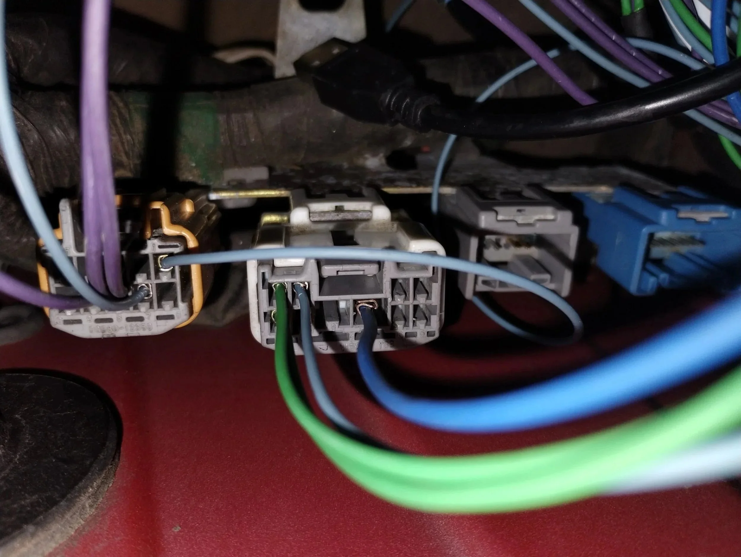
This was a good sign. I tried it once or twice more and it fires up each time. That told me my cams are timed right and my wiring harness is at least mostly correct. I wanted to figure out why my key wasn’t working, and my immediate thought was that there was something unique about the SMT cars vs. the manual cars. Since there was no clutch switch, it probably had some other safety check in the Bosch transmission controller to make sure it was in neutral.
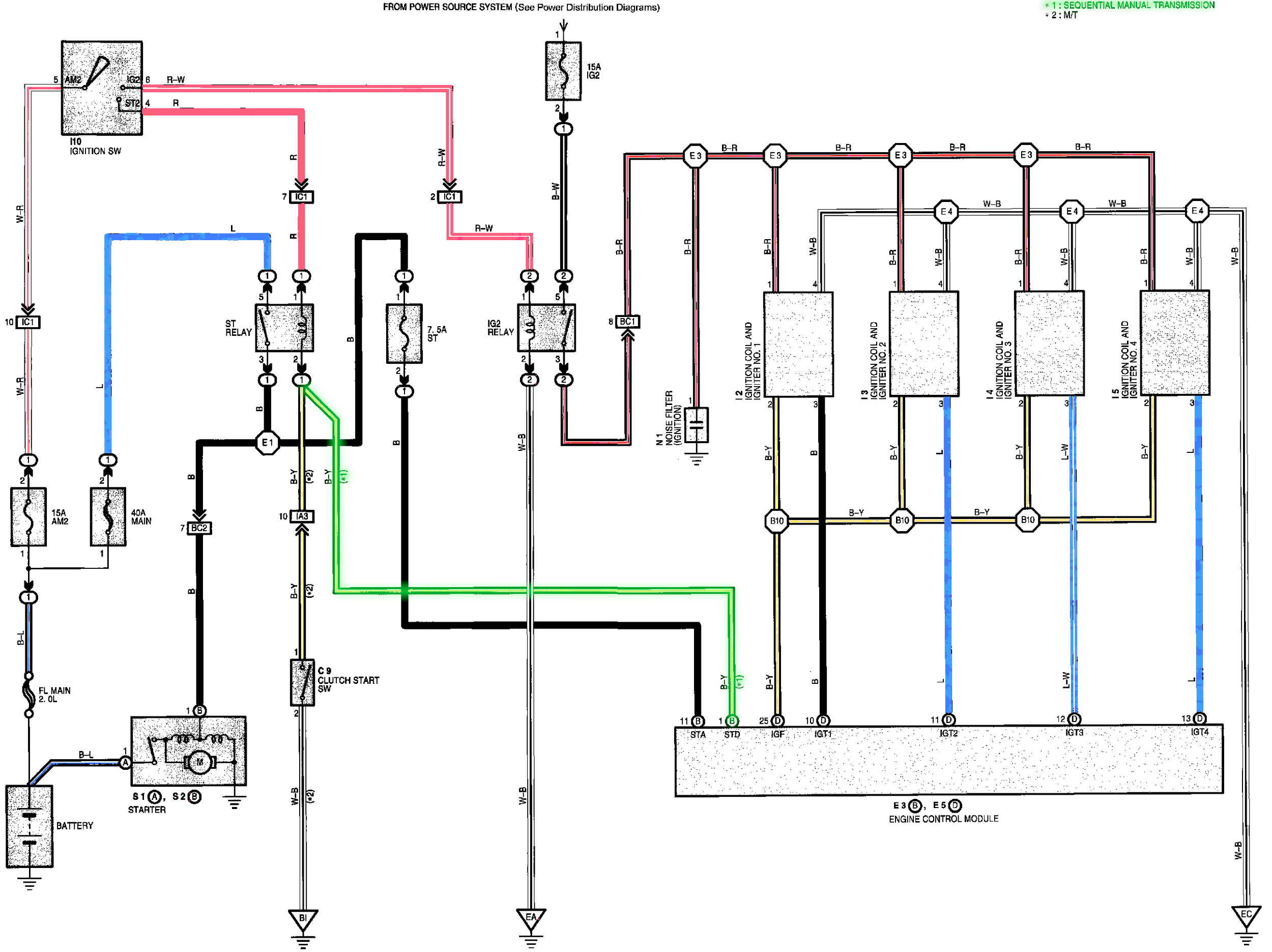
This seems to be the case. On the MT cars, pin 2 of the starter relay goes to the clutch switch then chassis ground. On SMT cars like mine, the ground side of that relay went to E3-1 on the ECU. All I need to do to make my key work is connect this wire to ground. I could’ve either removed the wire to reterminate it, grounding it in the car, or add a jumper inside of the FMW body controller, which is where said wire was terminated. Note that doing it this way skips a clutch start switch, which you may or may not desire, and may or may not be required in your area. I am free to remove this, and I prefer not having one anyway.
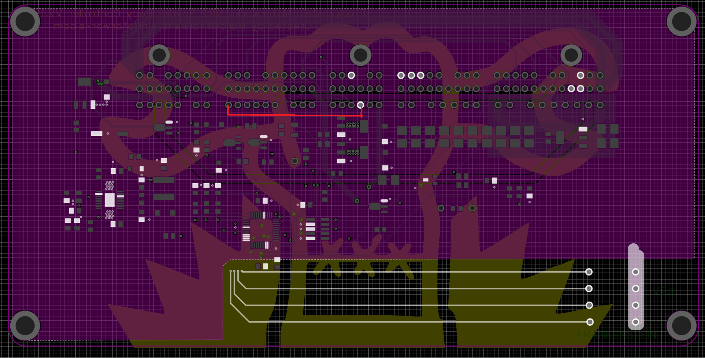
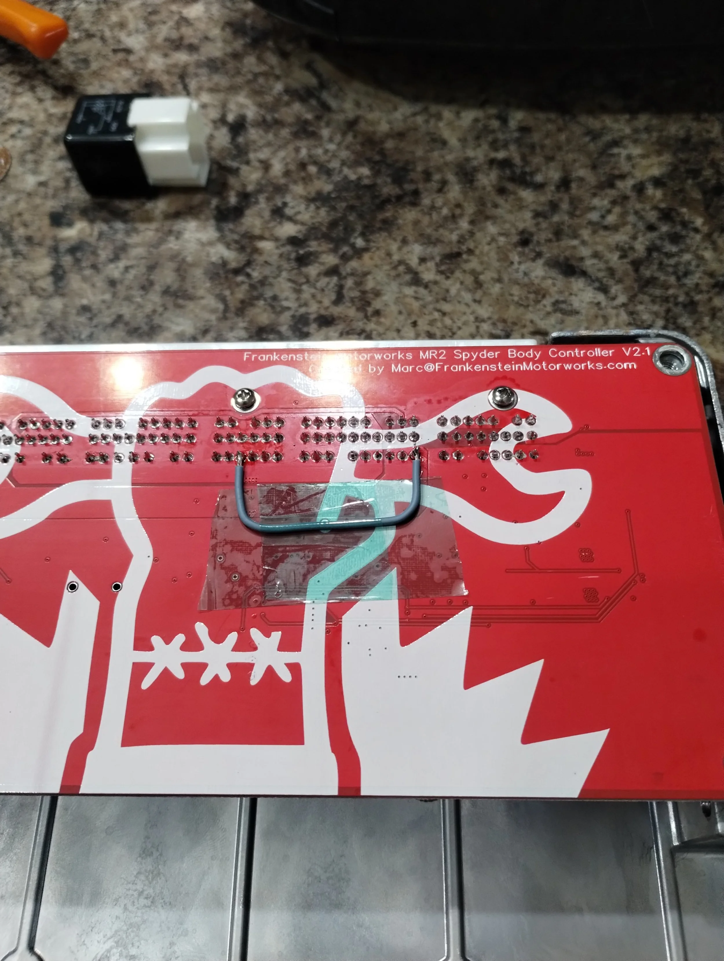
I mentioned this to Marc and he immediately figured out where a jumper could be used to solve my problem. Jumping E3-1 to 17P-4, which is on the ground plane of this body controller. This subsequently goes to engine ground through the rest of the harness. I kept getting tripped up on the mirrored image, Marc wanted me to go on the top side of the PCB, but I couldn’t see a way to feasibly get a wire in there and solder it. I added a little kapton tape as some strain relief on this wire.
Plug everything back in, and… nothing.
Oh yeah, I had removed the starter relay. That ought to do it. aaand… nothing.
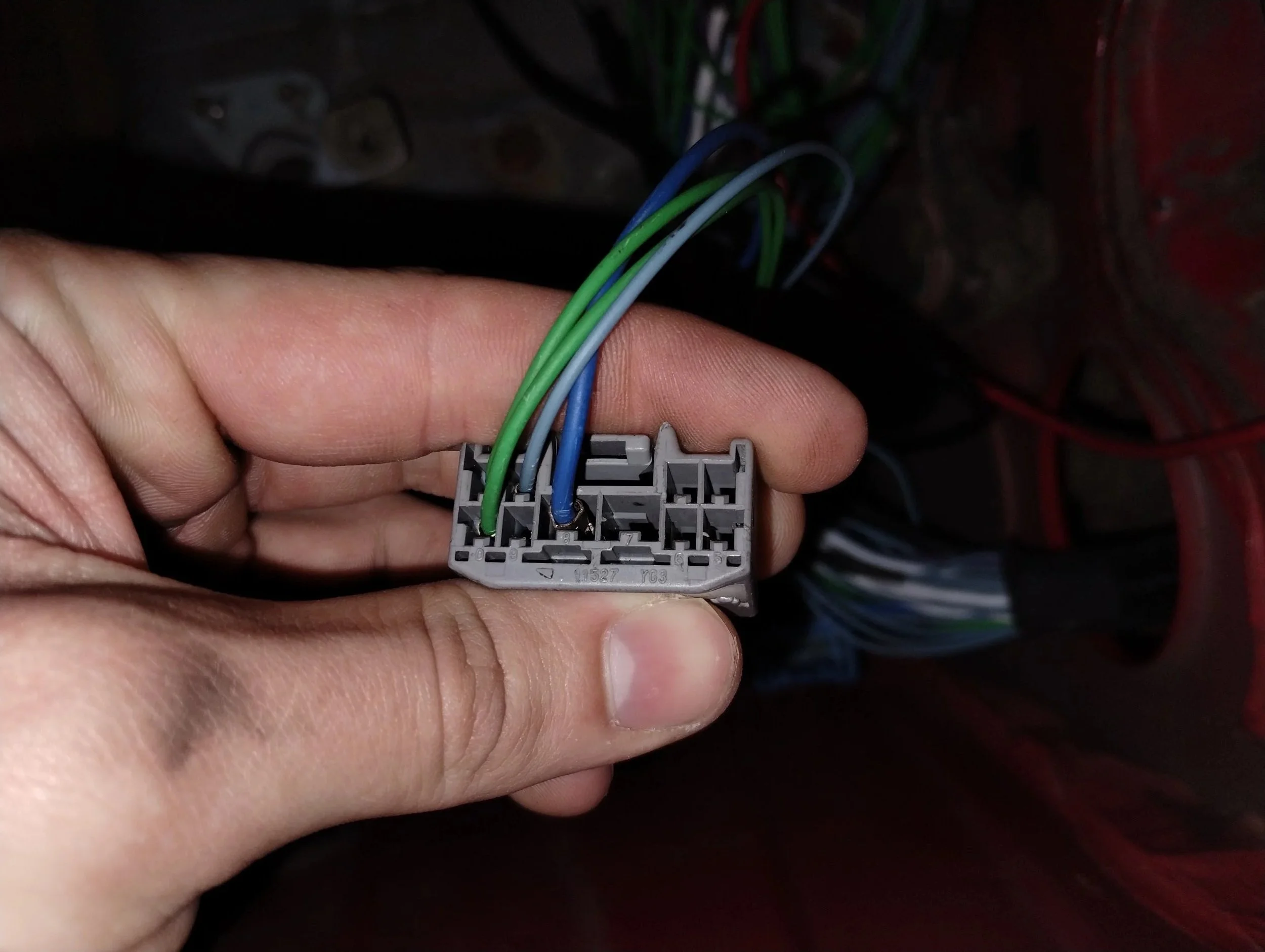
After checking a few things, I realized my starter solenoid wire was going to BC2-8, and it was supposed to be terminated at BC2-7. Silly me. Fixed that, then tried the key, and it finally worked! No longer must I lean over my engine bay to jump start my own car.
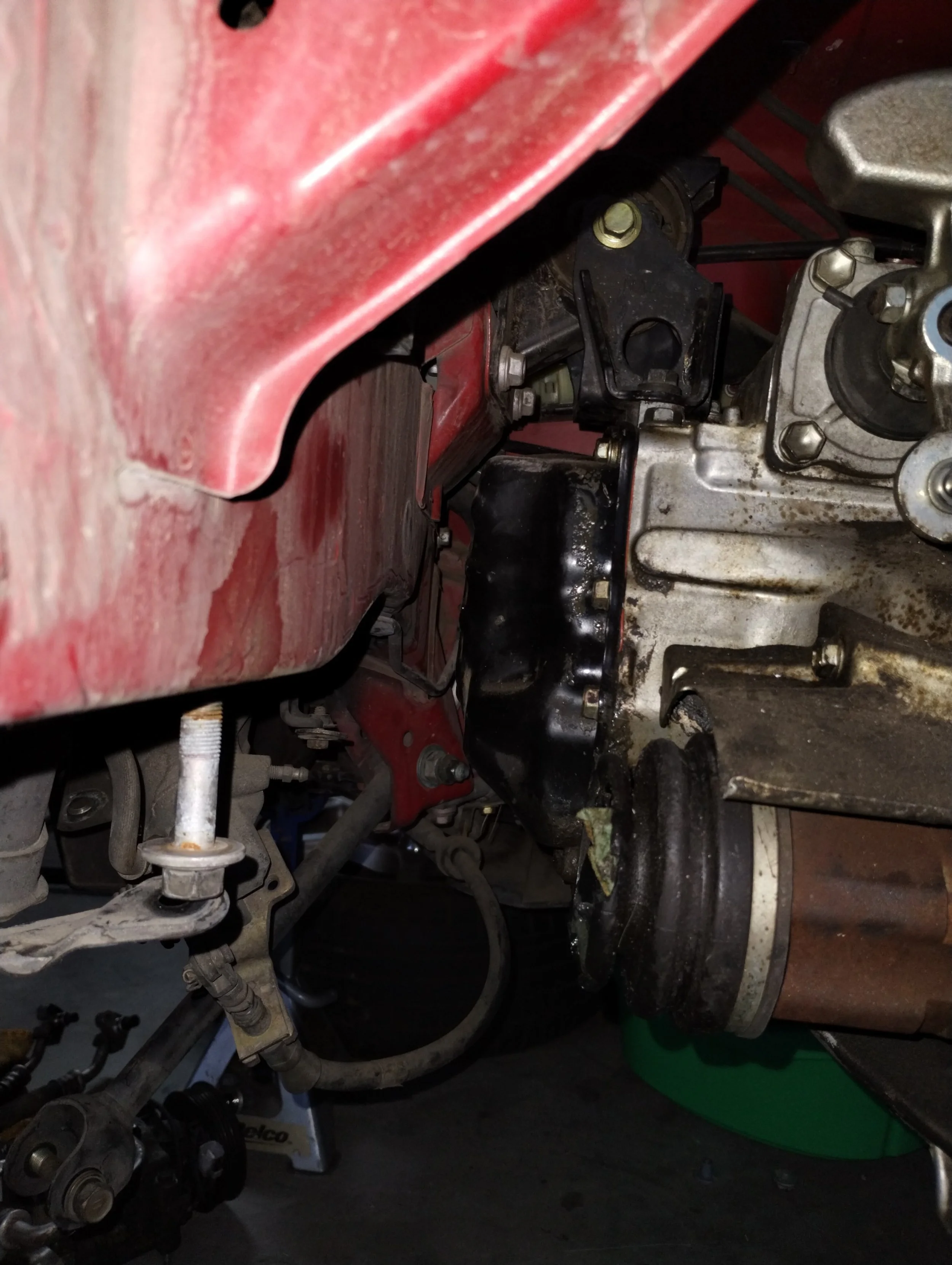
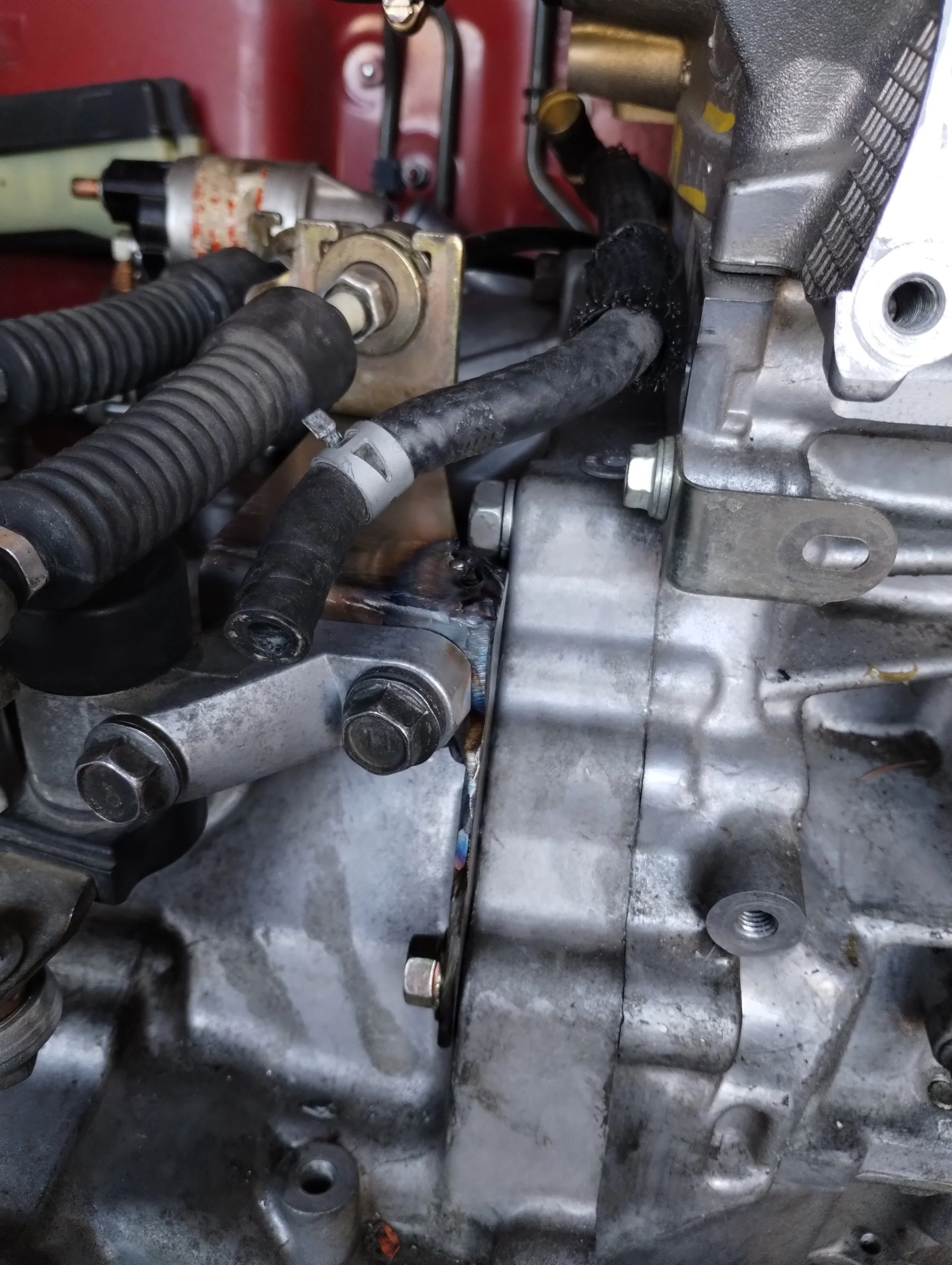
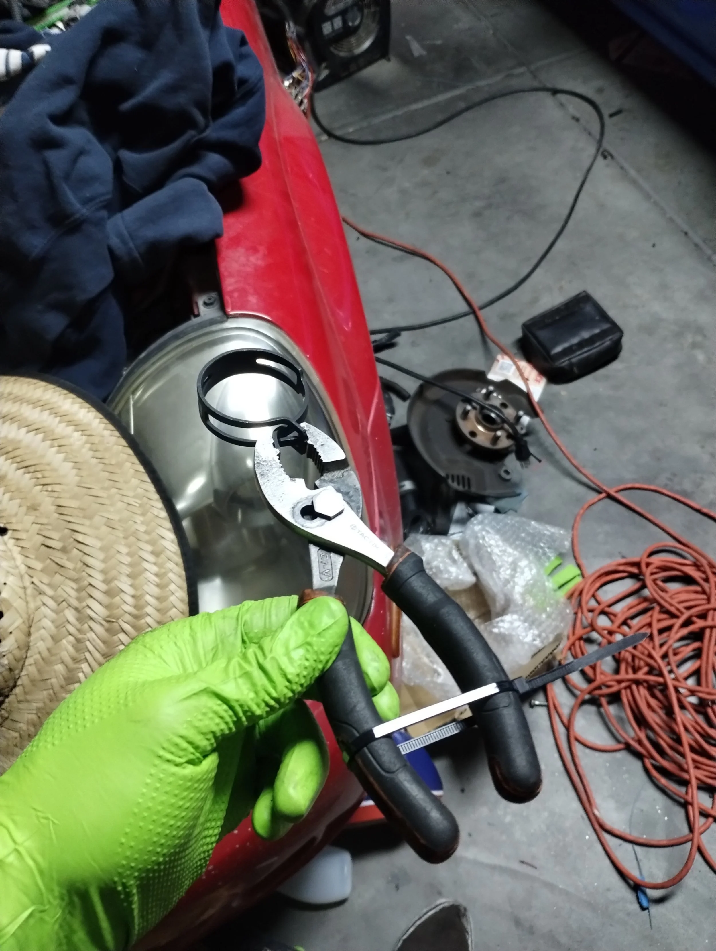
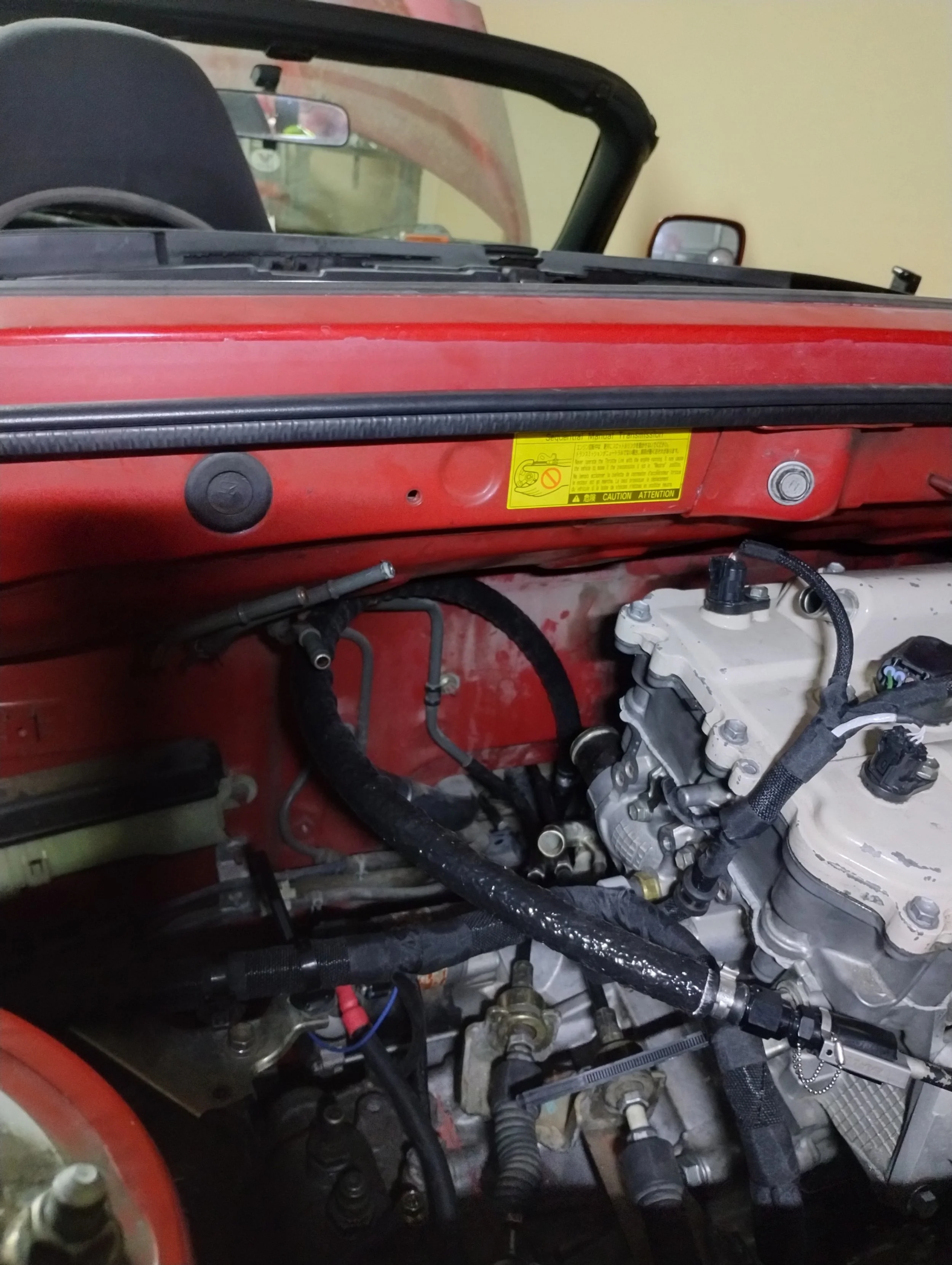
Since the car was able to start without issues, I could finally start buttoning up the last few bits. First and foremost: plumbing. Marc generally refers to the coolant hose as the hardest part of the swap. It’s a very tight area, and it’s a real squeeze to get the clamps on. He recommends some kind of ratcheting pliers, which I don’t have. I did the next best thing and pre-compressed the clamps and ziptied my pliers. This allowed me to get the hose on, with clamps, then cut the zipties to release. This one will be really fun to remove in the future.
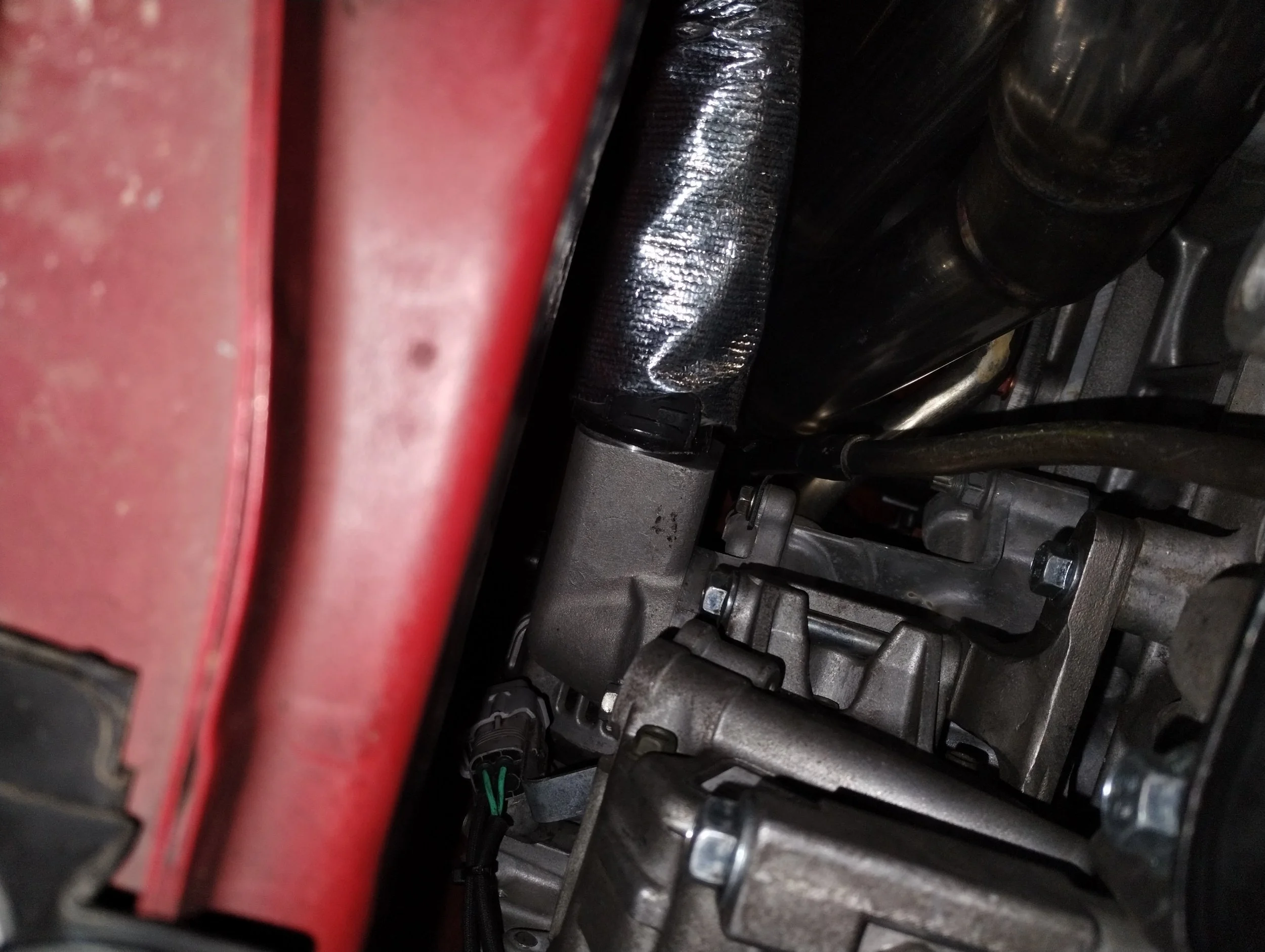
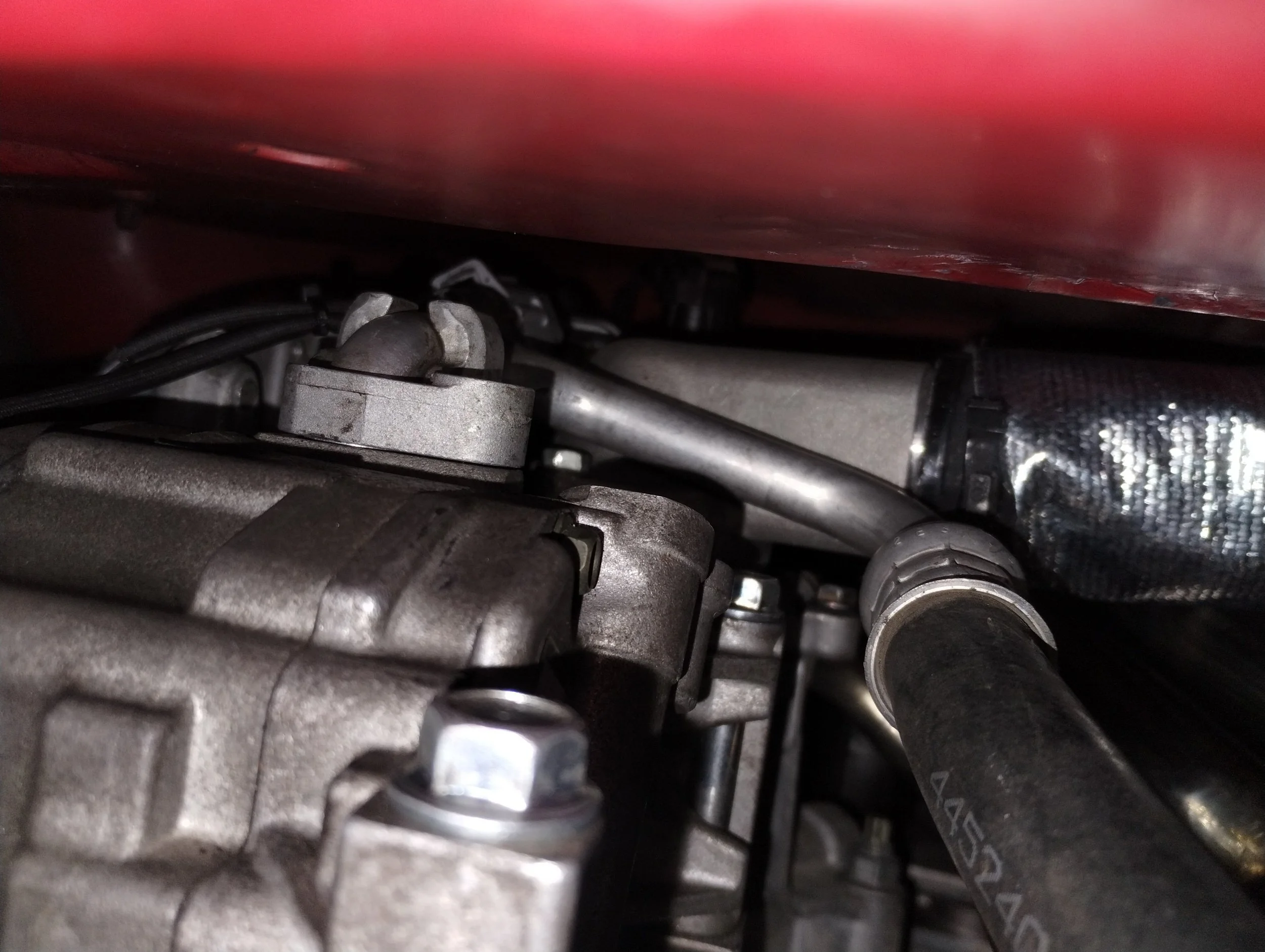
While in this general area it’s a good time to install my AC lines. I’ve heard you have to do while the engine is out of the car, but I found this to not be necessary. I had to clearance the lines just slightly. On the suction line, I had to bend it just slightly down, and changed the thermostat stud out for a bolt. Marc said this is typically a bolt, so I’m not sure why I had a stud there. That might have been me, or it could have been a Max move. On the discharge line (not pictured) ground away part of the clamp and bent the line slightly towards the engine to clear the firewall. Clamp? Not sure what to call it. That part that looks like a Lego hand holding the pipe. I’d like to add a small heat shield between the header and AC lines, there’s a pretty significant air gap but it still seems a little close for comfort.
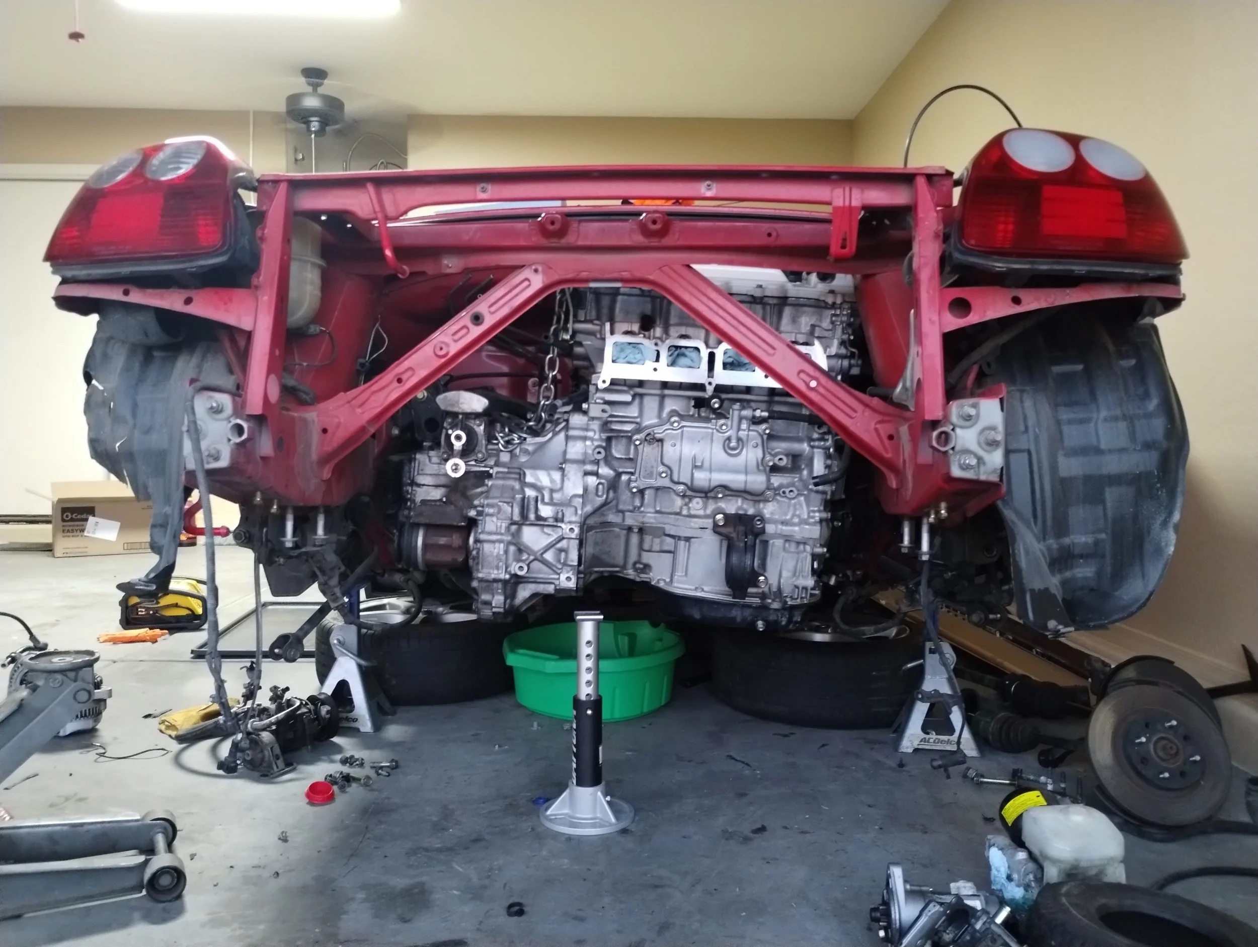
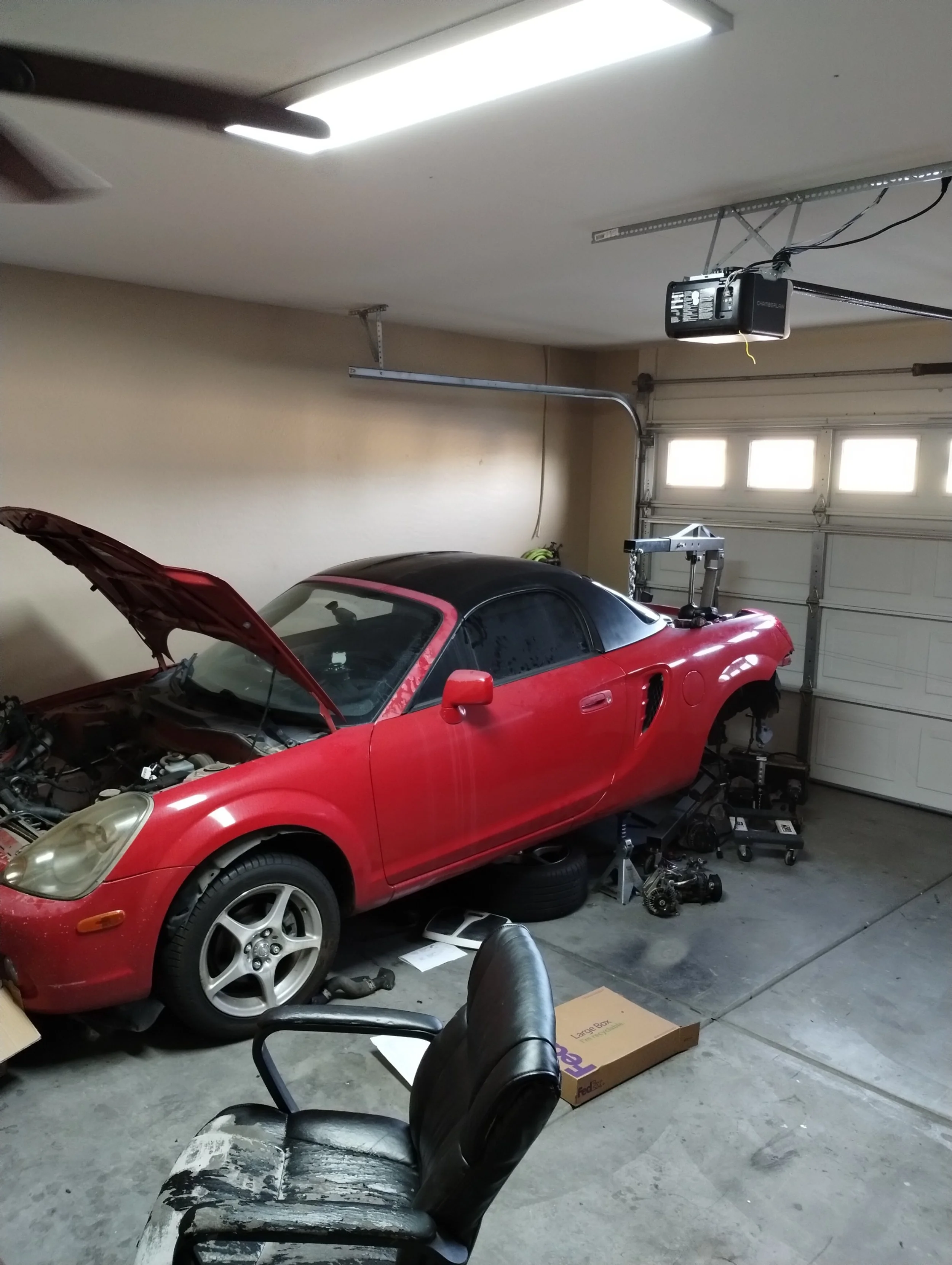
This felt like a good time to put the rear suspension back together and roll it outside for a minute. I needed to get under the front of the car for a few things, and there was way too much stuff in front of the car, and I couldn’t work around it. Cue a cleaning montage. This is where we “get the funk out”.
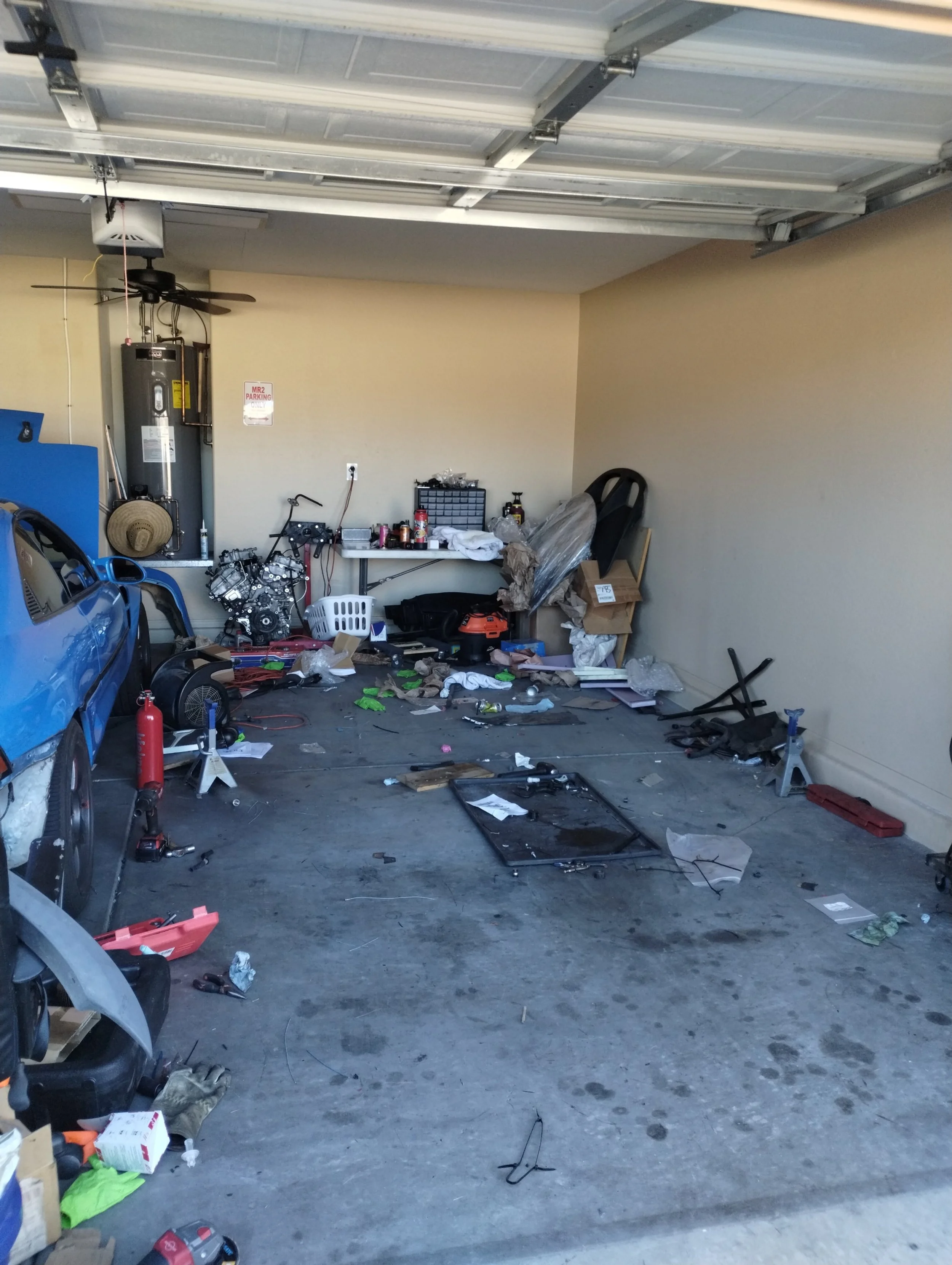
A proper mess. I assure you this was all cleaned
I could now walk entirely around the car. I found bolts-o-plenty, missing tools, and the lost city of Atlantis. All tools went back in their correct locations, all trash went in the trash. After my 3 hour cleaning session, I had to get the car back inside, or fight my HOA. My driveway slopes uphill, and while I can push the car up by hand alone, given it’s so light, I was tired, and the tires were flat, so that wasn’t happening. At a glance, if I put the crash bar back on, that would seem to be about the same height as my RAV4’s trailer hitch.
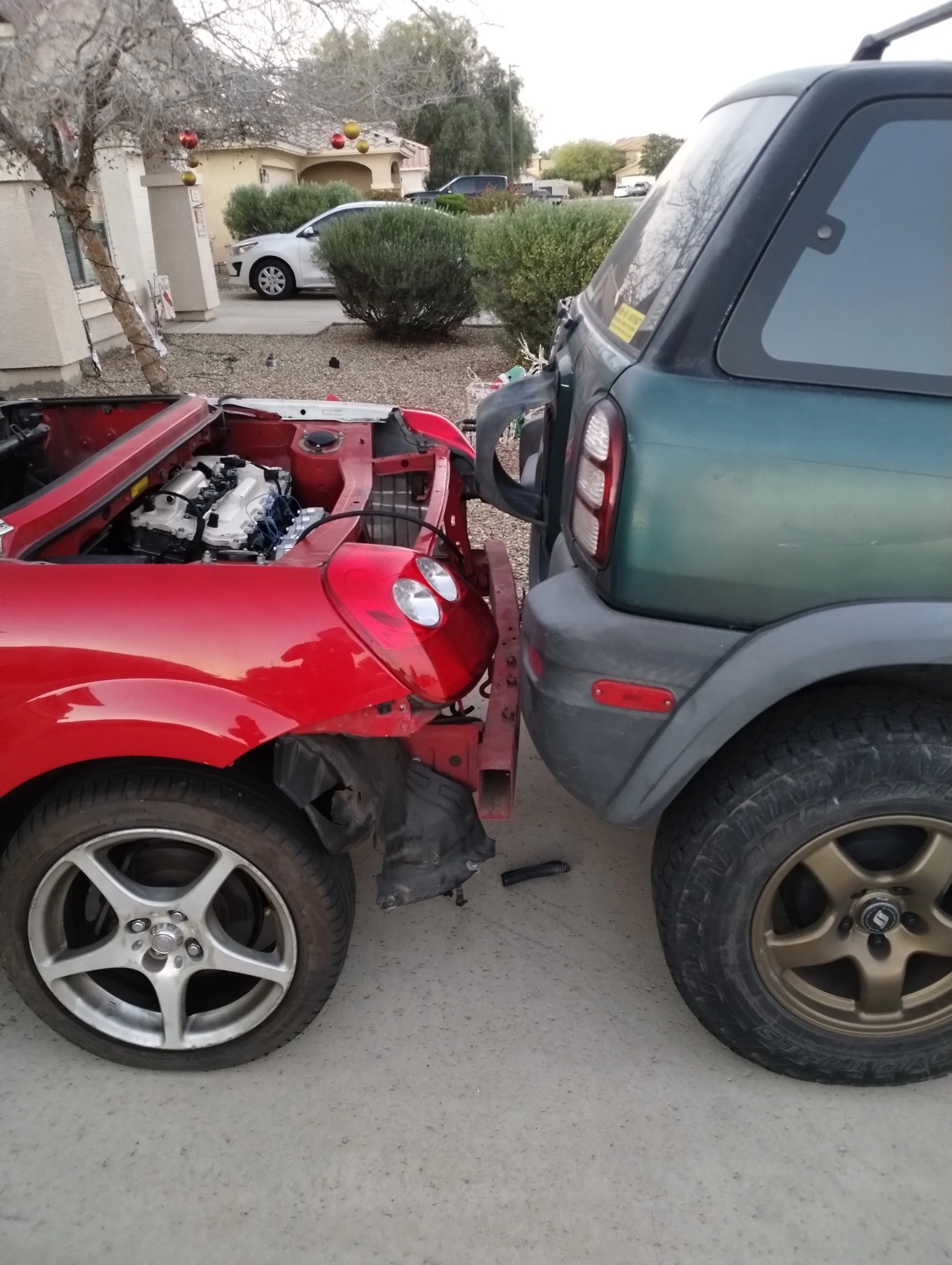
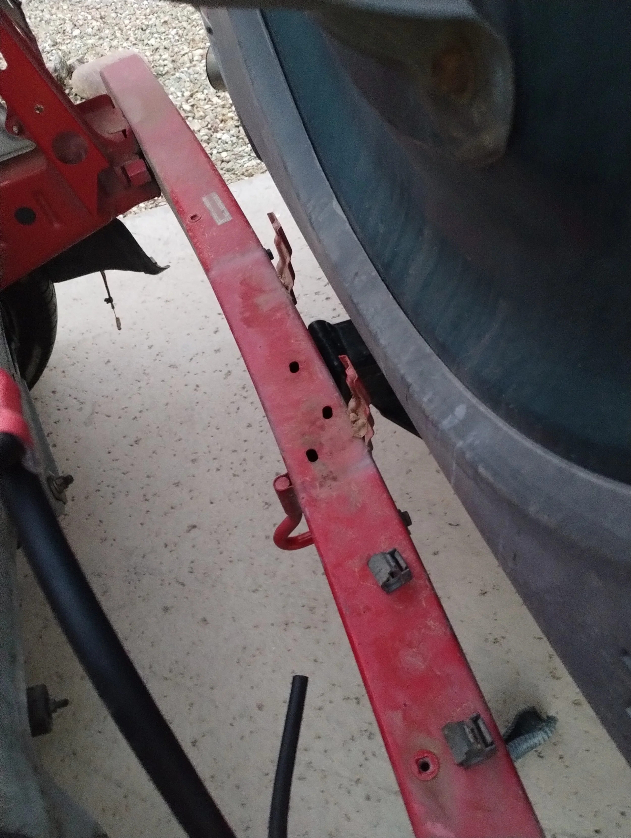
Just like that, I backed up a few feet, adjusted the steering wheel, backed up another foot, repeated until the car was back in the garage. This is honestly one of the funniest things I’ve ever done.
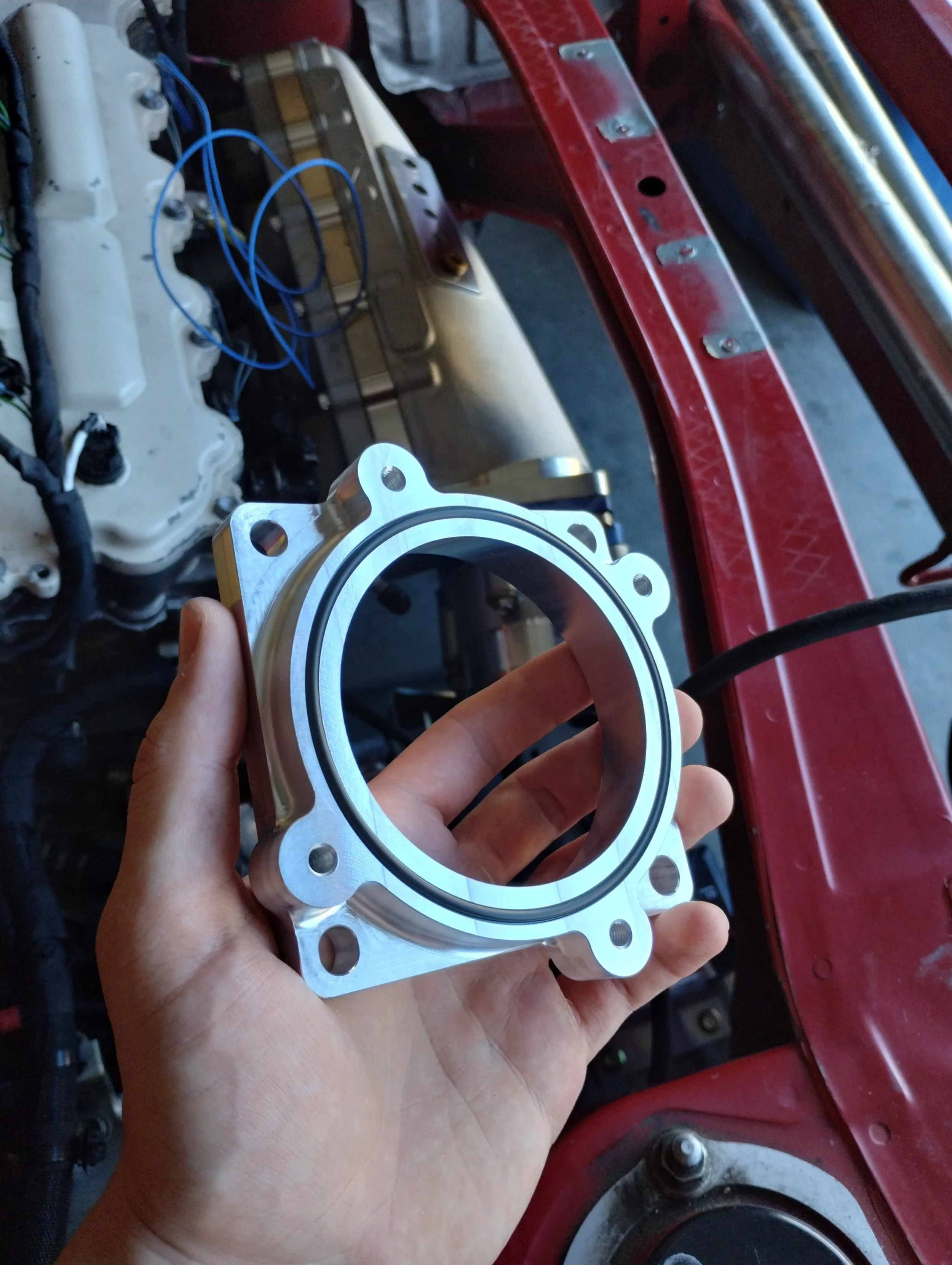
Since then, I’ve received a few packages. One, Marc machined me (and two friends) the throttle body adapter I designed, and it’s beautiful. The next package I got had the rest of my fuel line parts. You might see some problem arising.
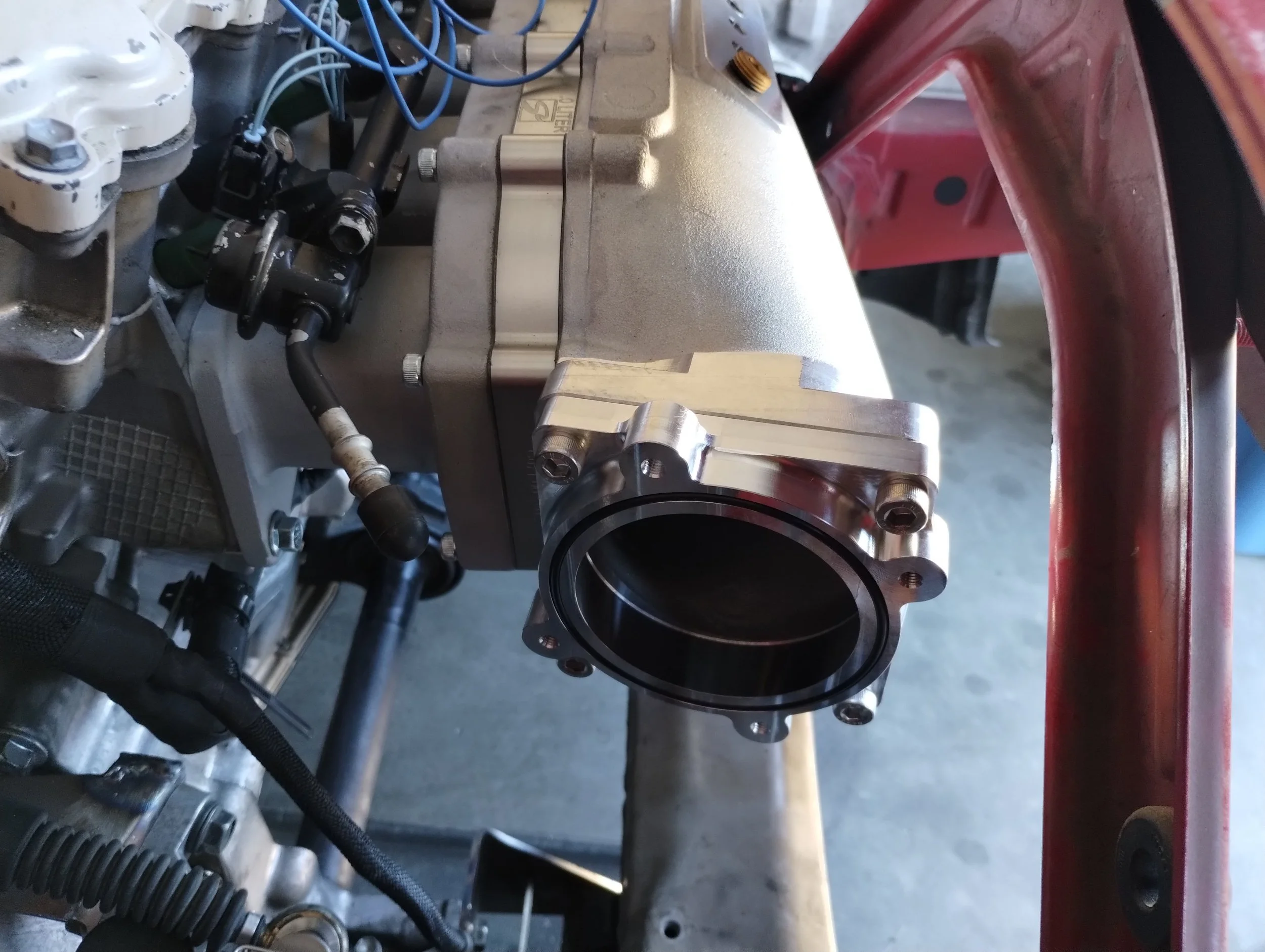
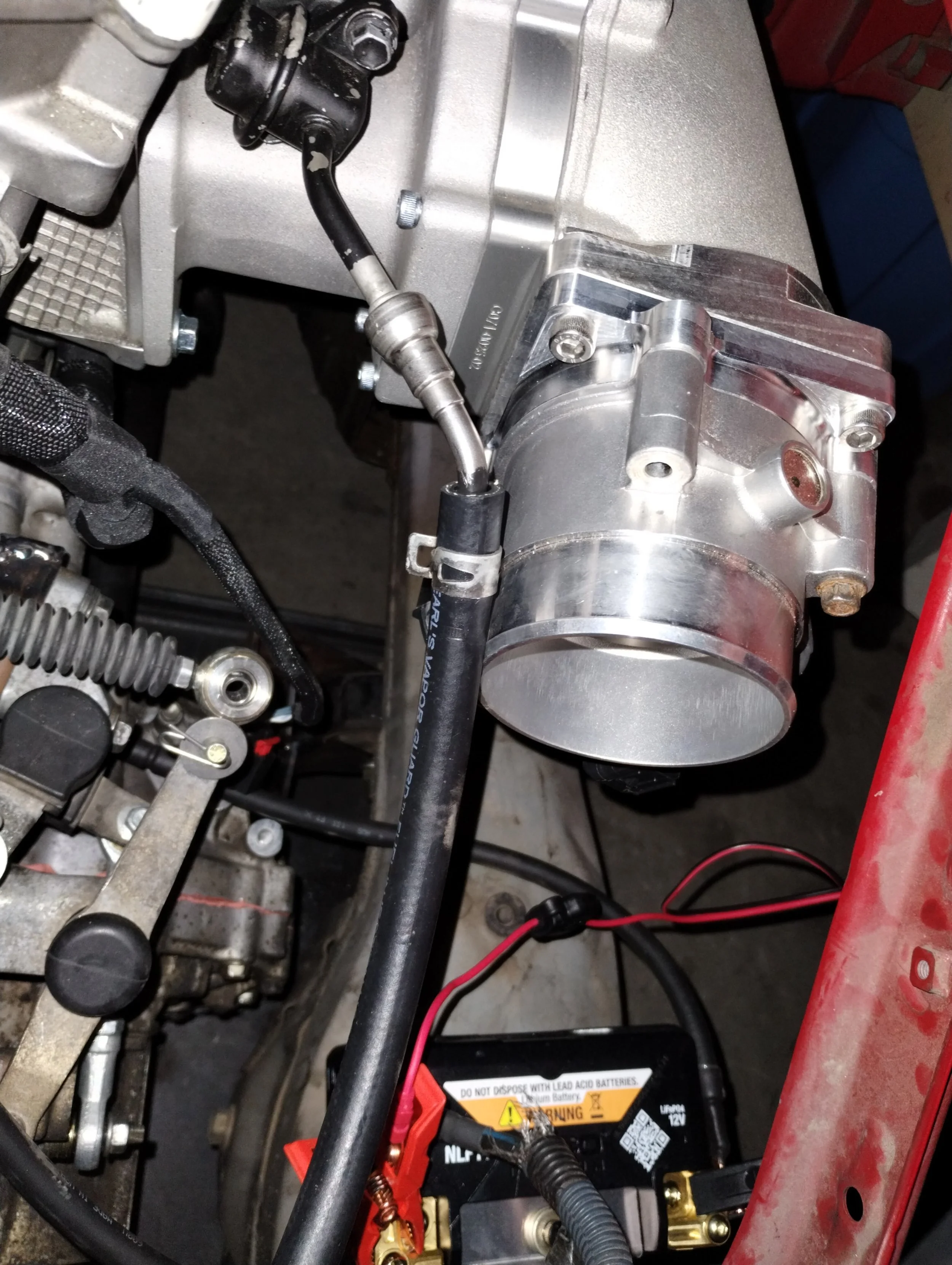
See that pressure damper on the fuel rail? I had previously flipped it around because it made some light contact with this FMW intake. Normally, it points slightly forward, instead of rearward as shown. I thought there would be enough room, but no matter what, my fuel line would end up contacting the throttle body. So, back to the drawing board on that one. I thought about bending it to straighten it out, but decided that was not my best course of action. Marc told me to shave off some material on the intake and shave off some of a bolt head.
I didn’t have to take off much, I just used a file and went slow. It’s enough where I could at least slip a paper between the damper and intake. After I got that sorted, I shortened my fuel line, added fiberglass heat sleeve, crimped on the rest of the fittings, and plugged everything in to check for leaks. After that, we were good to go. It’s a little longer than necessary, but that’s fine. I later added a couple P clamps on the firewall to fix the hose in place.
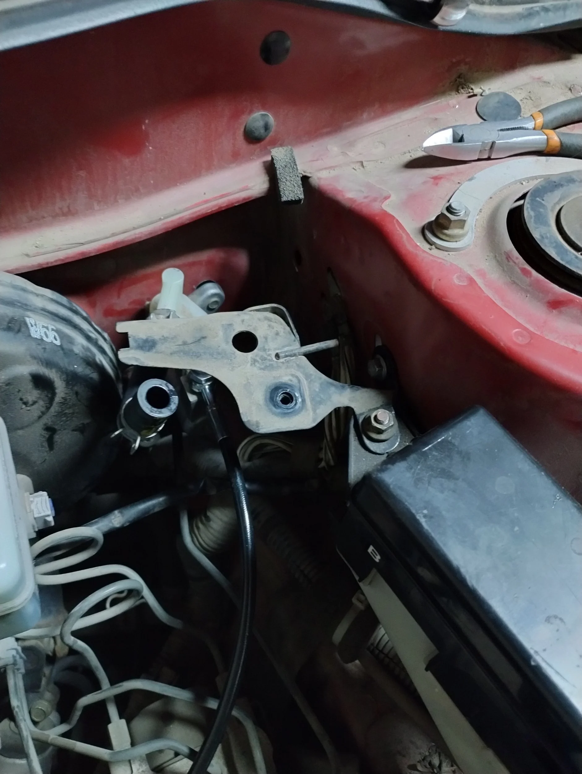
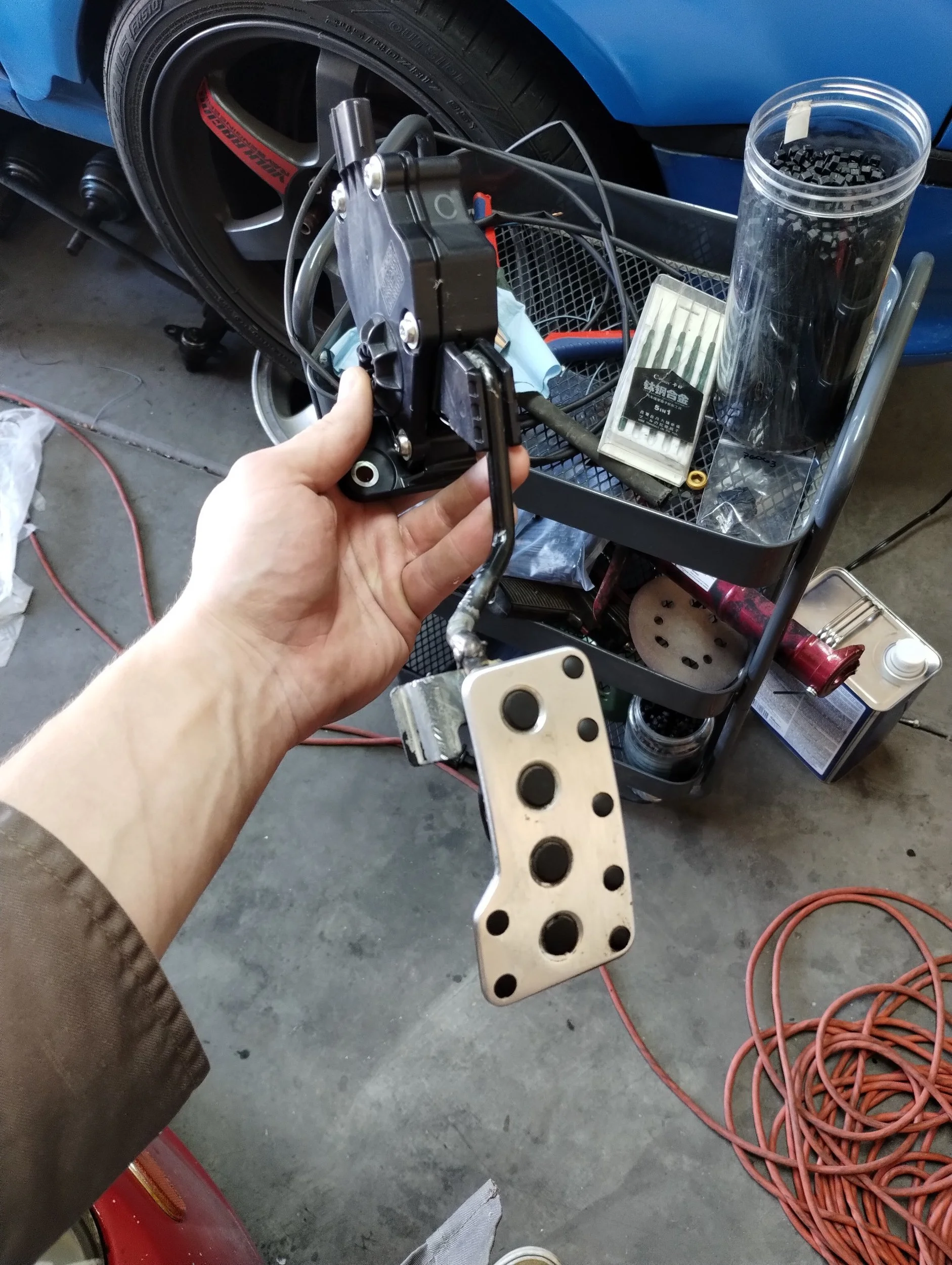
Next on the list of getting it driving was installing a clutch pedal, slave cylinder, and the hydraulic line. I went back and forth on whether I’d run a hardline or buy a clutch line from MWR. For the sake of time, I bought the soft line. I don’t have any of the flaring tools, or even a bench vise, so I decided this was my best option. This goes straight from the clutch master to the slave, with no breaks between. First, I need a master cylinder. Spyder masters are fairly expensive these days, and only available used. Looking around, it seems like the slave cylinder is shared with the first gen Scion tC. tC1s are plentiful at junkyards, so I got a used one there.
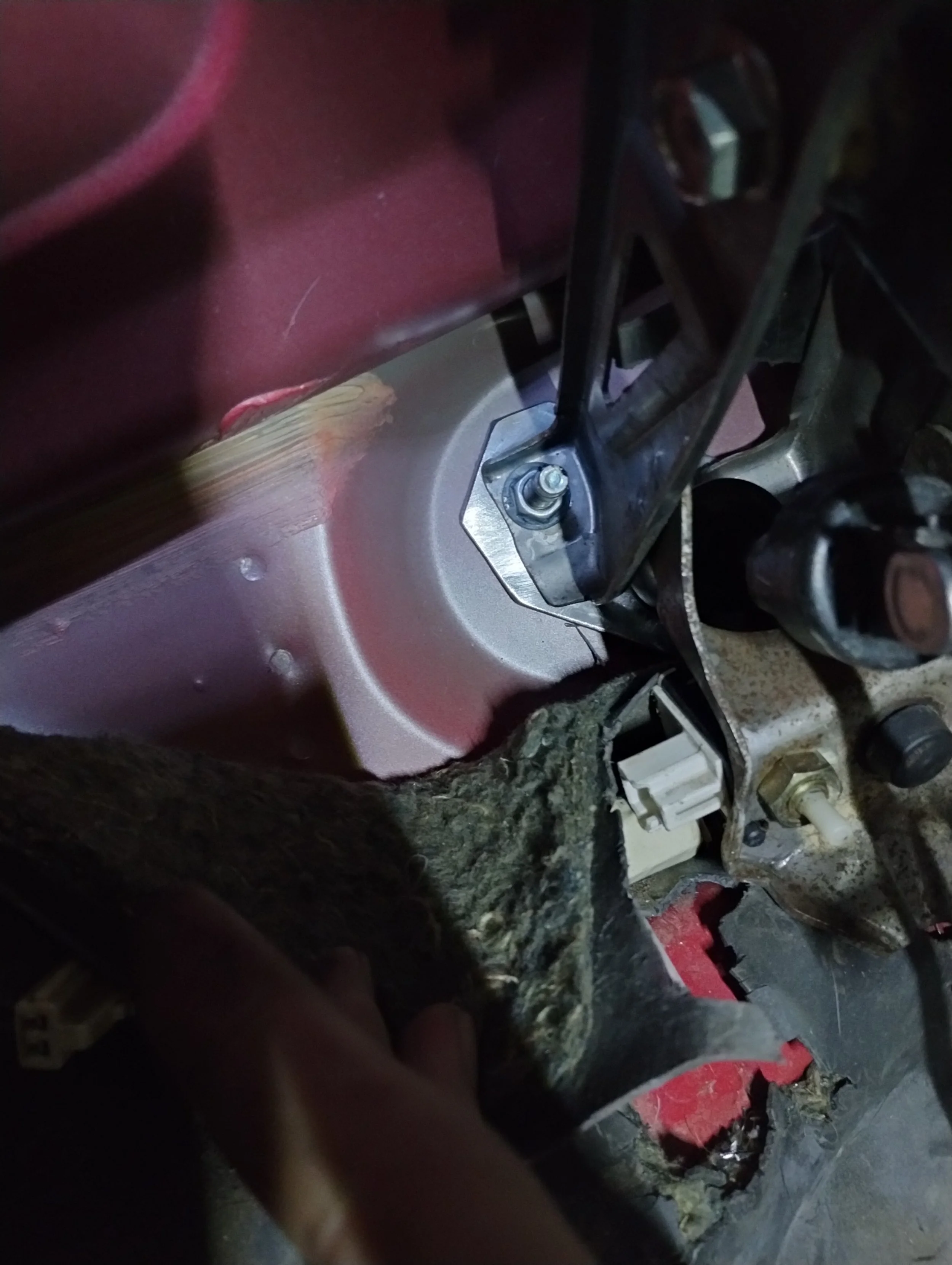

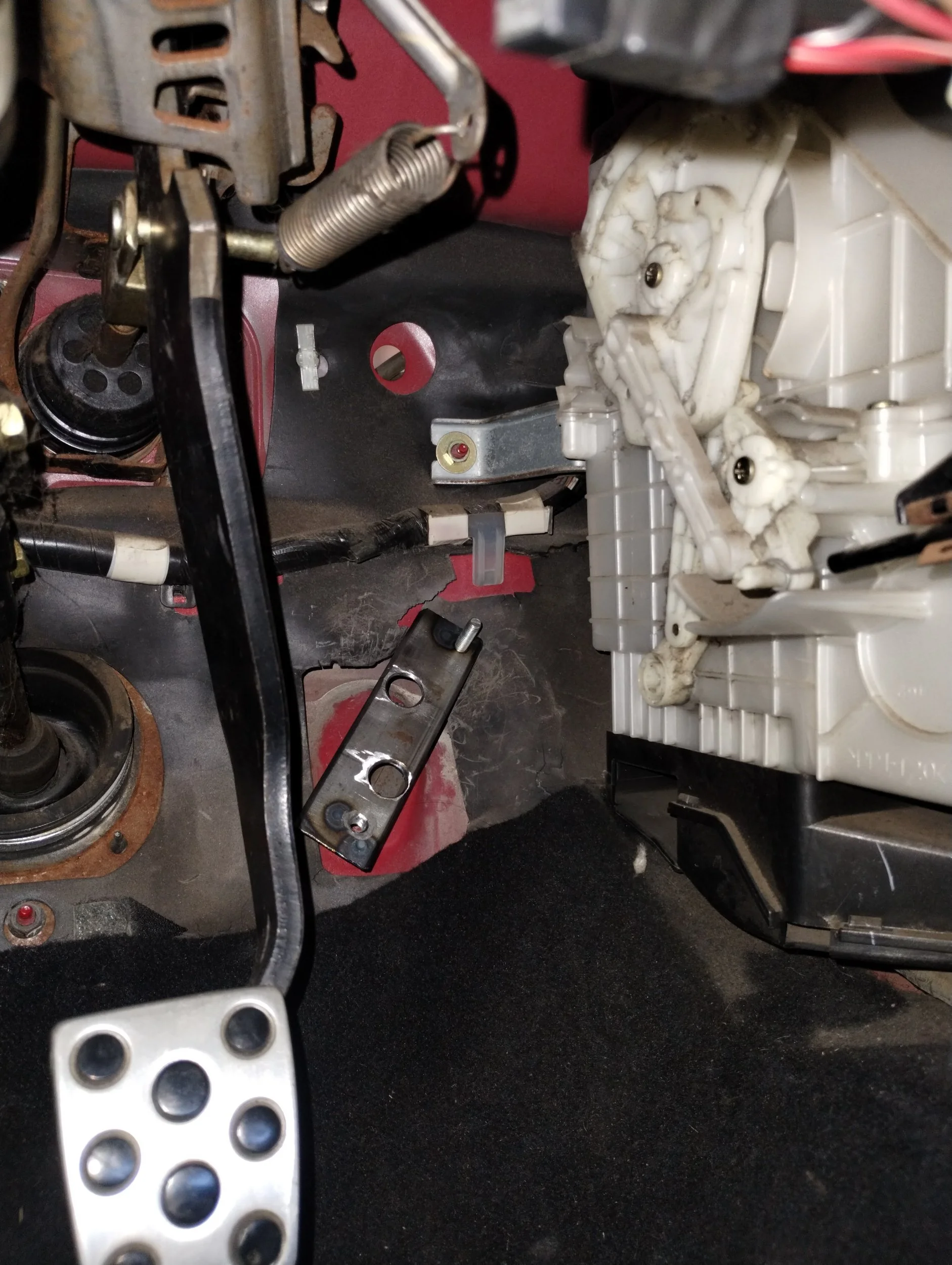
I got the drilling template from MWR. I don’t know if it was the template, or the way I printed it, but somehow my holes weren’t even close. I had to elongate all the holes in order to bolt the clutch pedal down. I’m not going to blame MWR, plenty of people have used this kit, so it must have been something I did wrong. Nobody knows. I was not comfortable with the supported area here, so I added a piece of steel in between the pedal and firewall to spread the load out. I also extended the pushrod slightly, I guess the tC pedal sits closer to the master. Easy, a coupler nut and small stud.
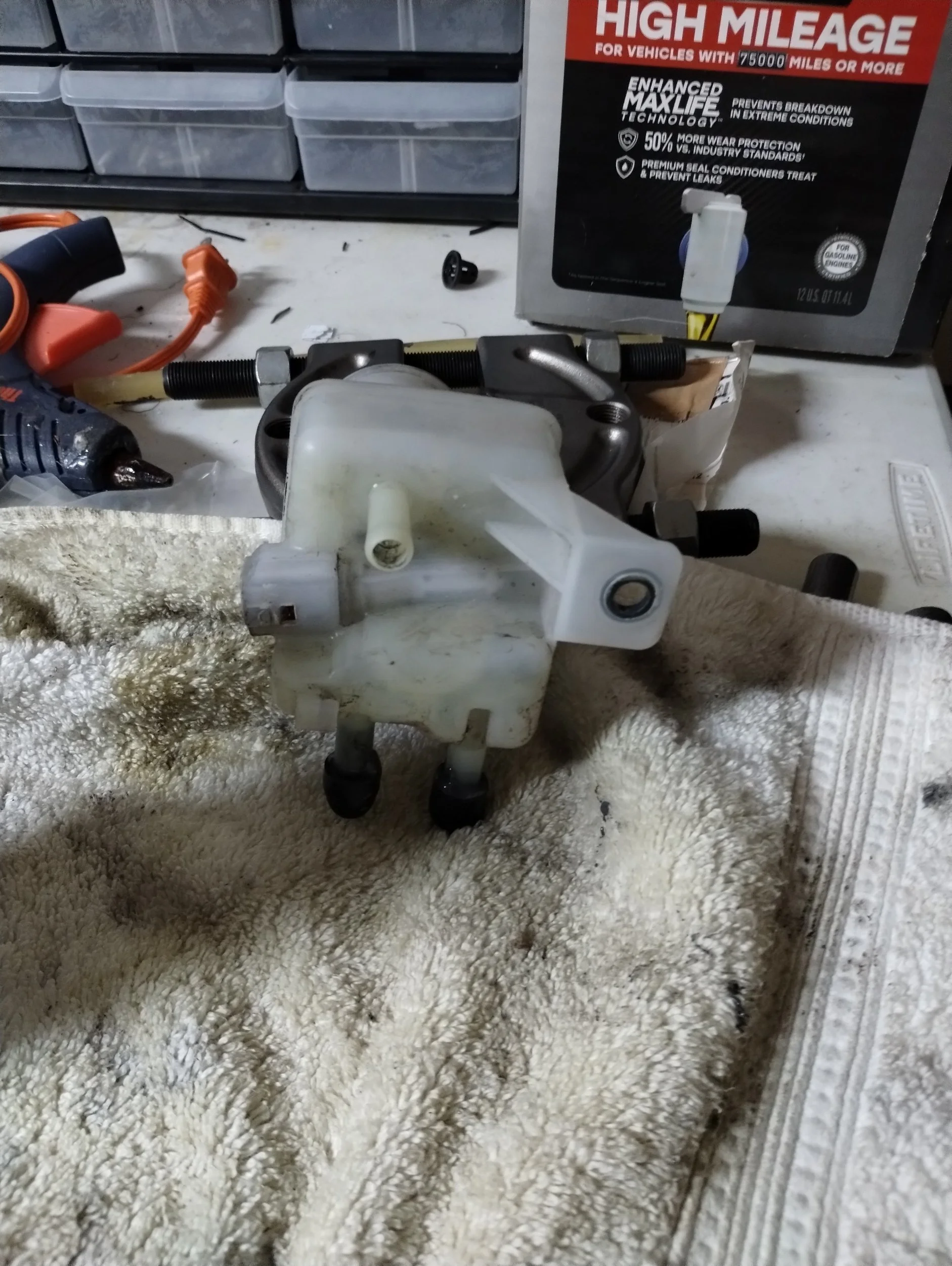
While the slave cylinder is shared between the Spyder and tC, the reservoir is not. The Spyder typically has a separate clutch reservoir directly mounted to the cylinder. Adding the brake reservoir from that junkyard tC was straightforward, I added a couple holes to bolt the bracket down. There are three outlets on this reservoir, one each for the front and rear brakes, and one for the clutch. I JB welded the two brake hose outlets since I’m only connecting it to the clutch master. In the future, I could theoretically get a different brake master “hat” that has the separate hoses. That’s gonna be a V2 change.
One final hiccup here, which is definitely not MWR’s fault. As I found out, a Spyder’s clutch slave cylinder uses an M12x1 fitting, and my E350’s clutch slave uses M10x1. Not the end of the world, I just had to order yet another adapter. After getting that, I had a functional clutch. I installed the hose and fitting off-camera. The MWR hose seems to be too long by maybe 8”, but better that than too short. I stuck some P-clamps on it and called it a day.
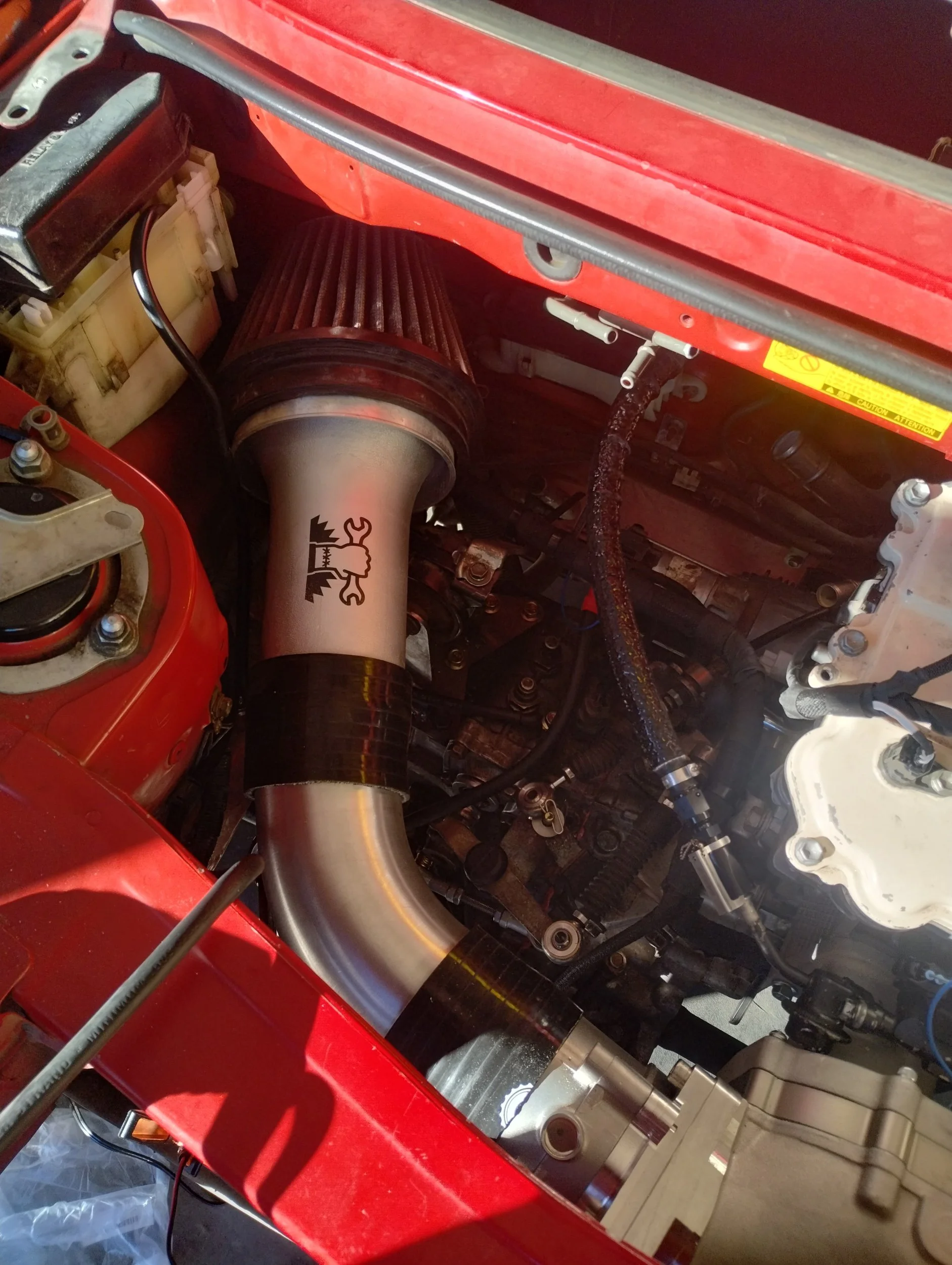
The intake was also straightforward. I ordered some 3.5” aluminum pipe on ebay, cut it to length, and added some couplers. I made a small stainless steel bracket, bent that to shape in my hydraulic press. It’s pretty tight in there, but it will work.
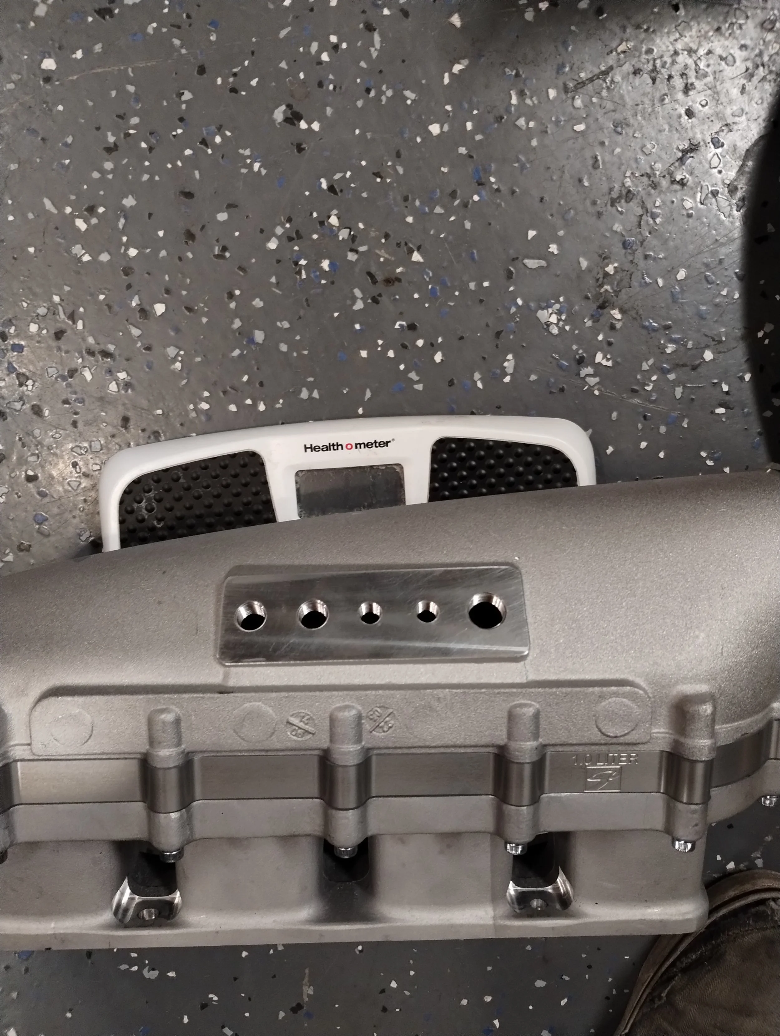
In a positive and surprising turn of events, Skunk2 gave me a clear answer on what thread sizes the intake manifold fittings are. 4x 1/8” NPT, 3x 1/4” NPT, and 1x 3/8" NPT. In my case, trying to keep the hoses somewhat hidden, I only used the three ports on the bottom, and plugging the top. 1x 3/16, for the ECU MAP sensor, and 2x 3/8s, one for the brake booster, and one for the air oil separator.
I realize that I’m due for a first real start. My test fire earlier was with a lack of MAF sensor. The way my Haltech is set up, it will stop injecting fuel out of safety. Now that it’s connected though…
This is obviously with no mufflers or anything. Seems like it was only running on one cylinder at first, then suddenly the other three came on, probably purging air from the fuel lines.
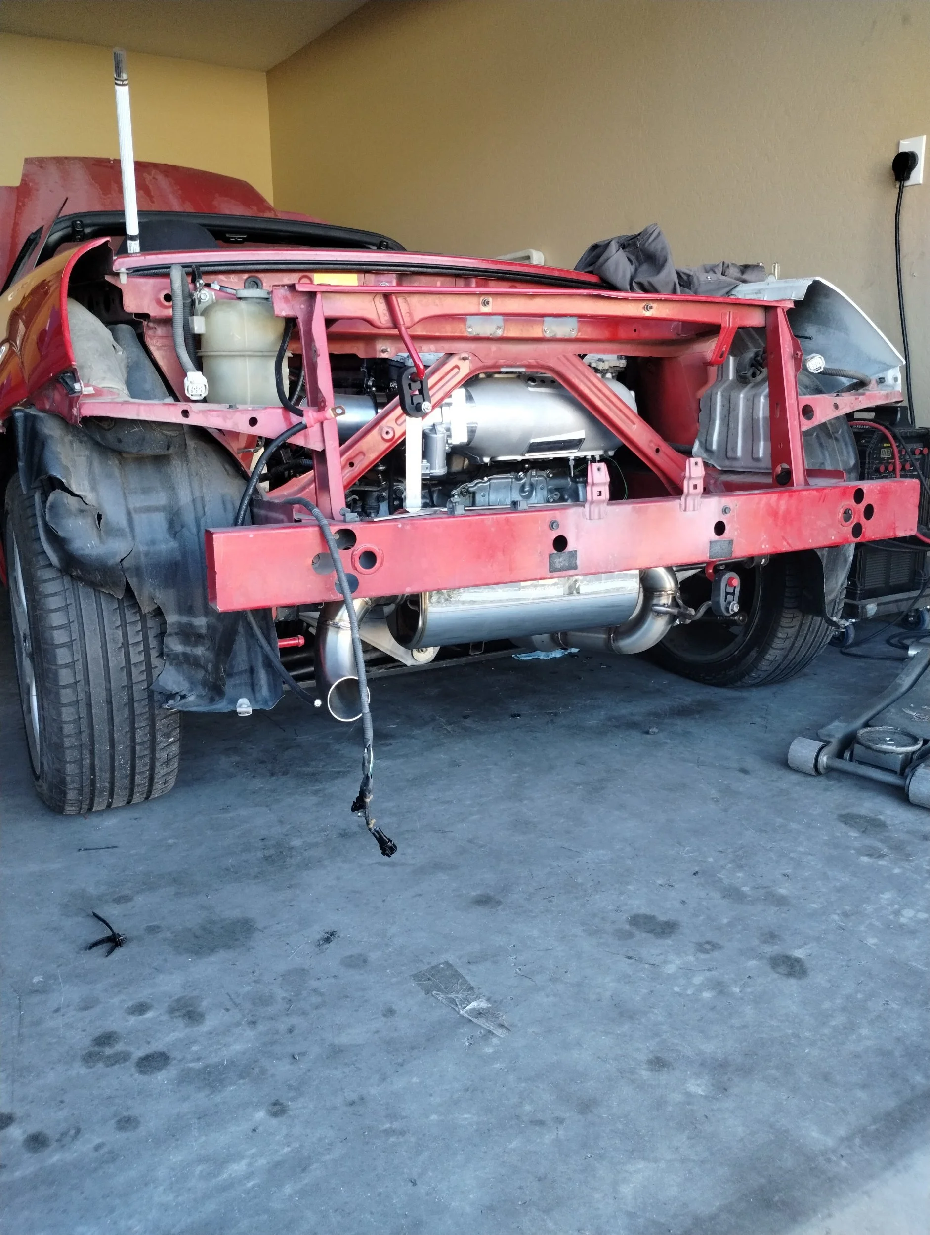
Back to exhaust. I’d like a dual center exit, similar to my SW20. Unfortunately, this isn’t very feasible in this car. Doable, but complicated. I chose to do a simpler single muffler setup. I went back and forth on the routing. Originally I wanted to run it above the subframe, but for a few reasons I opted against this. For one, it would get the exhaust really close to my vacuum lines and wiring harness. This can be mitigated with heat sleeves/shields, but that’s more stuff to do before driving this car. Second, I was out of V bands. I thought I had more, but nope. Putting the exhaust above the subframe would “trap” the exhaust in place, requiring me to remove the subframe and sway bar to remove it. Sounds like a pain, in the future. Going underneath the subframe has its own set of problems too, including ground clearance.
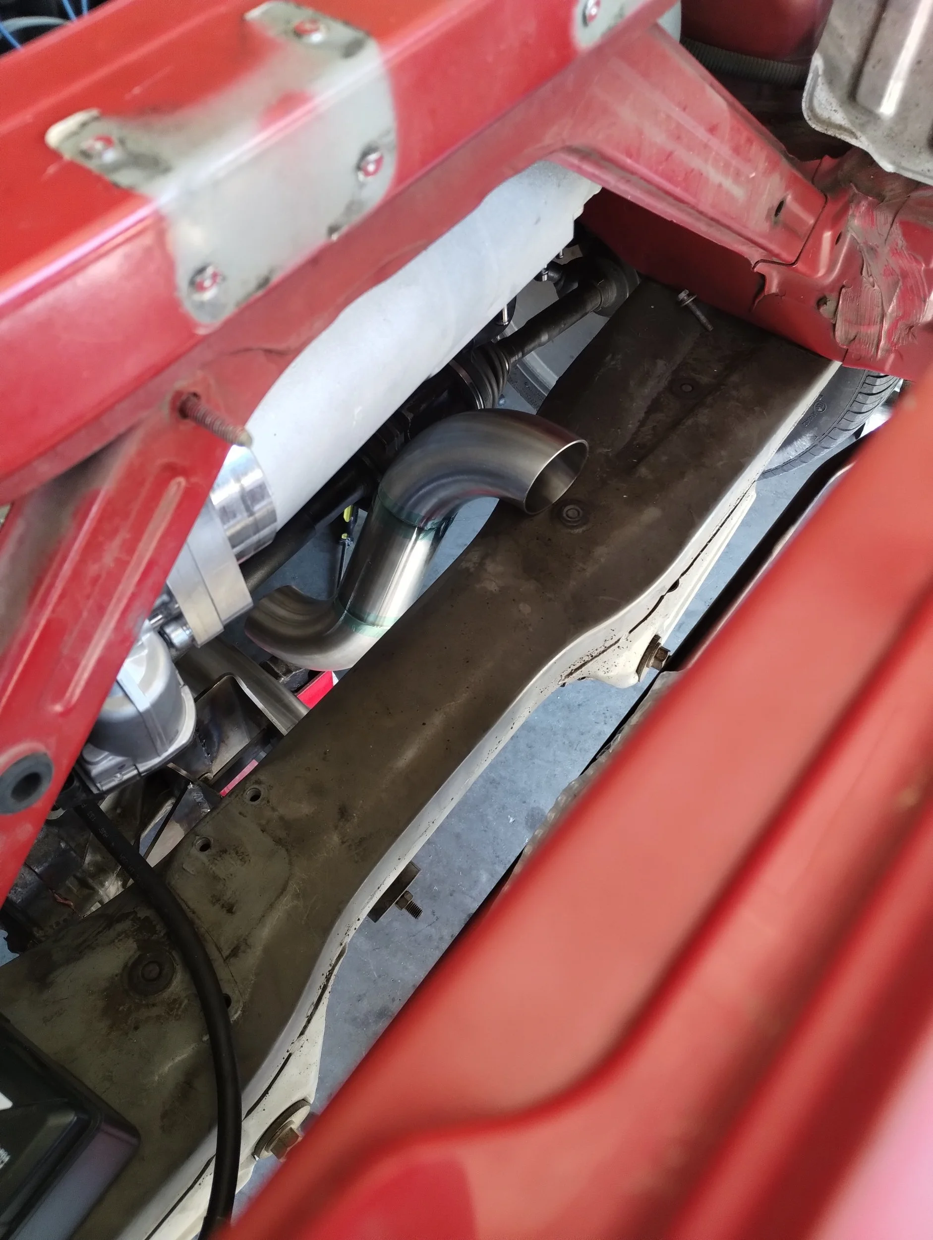
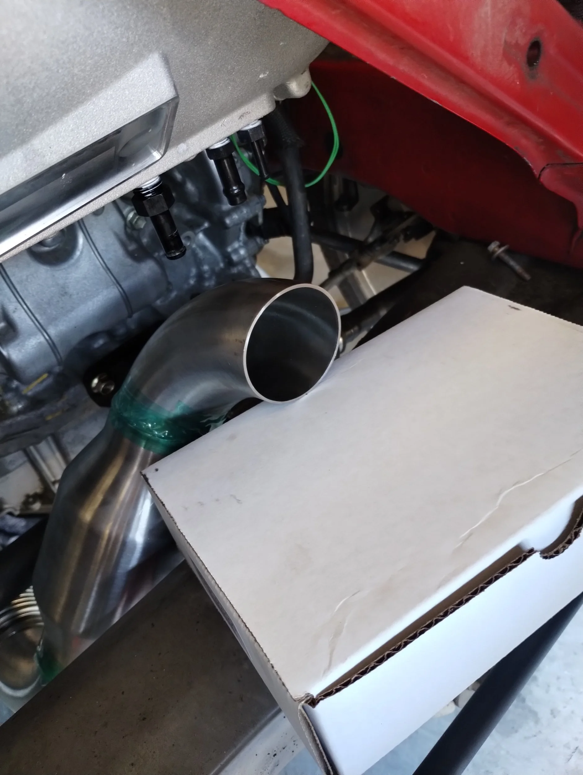
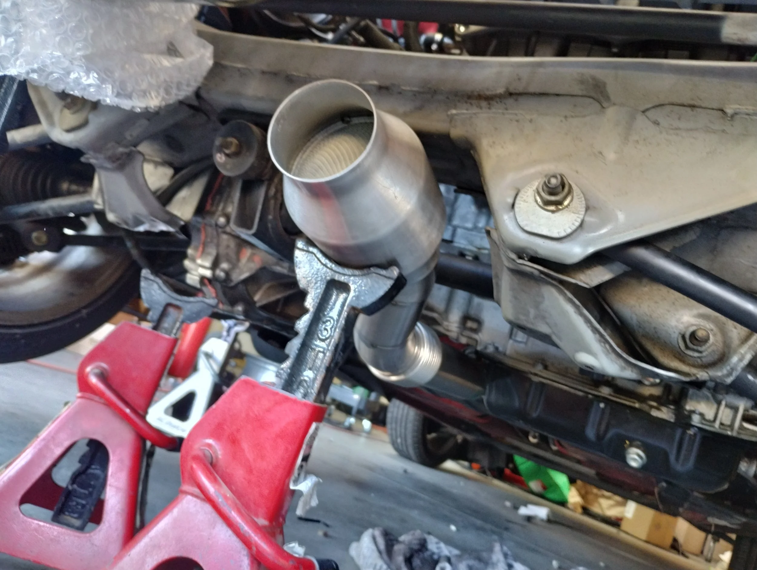
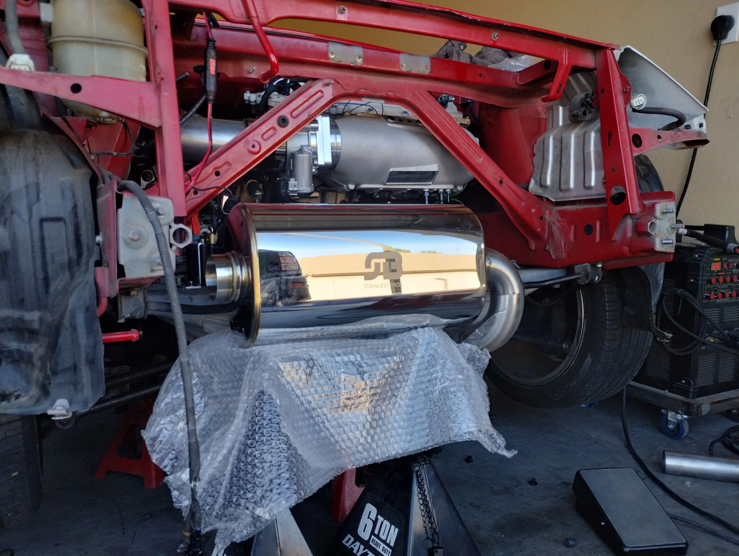
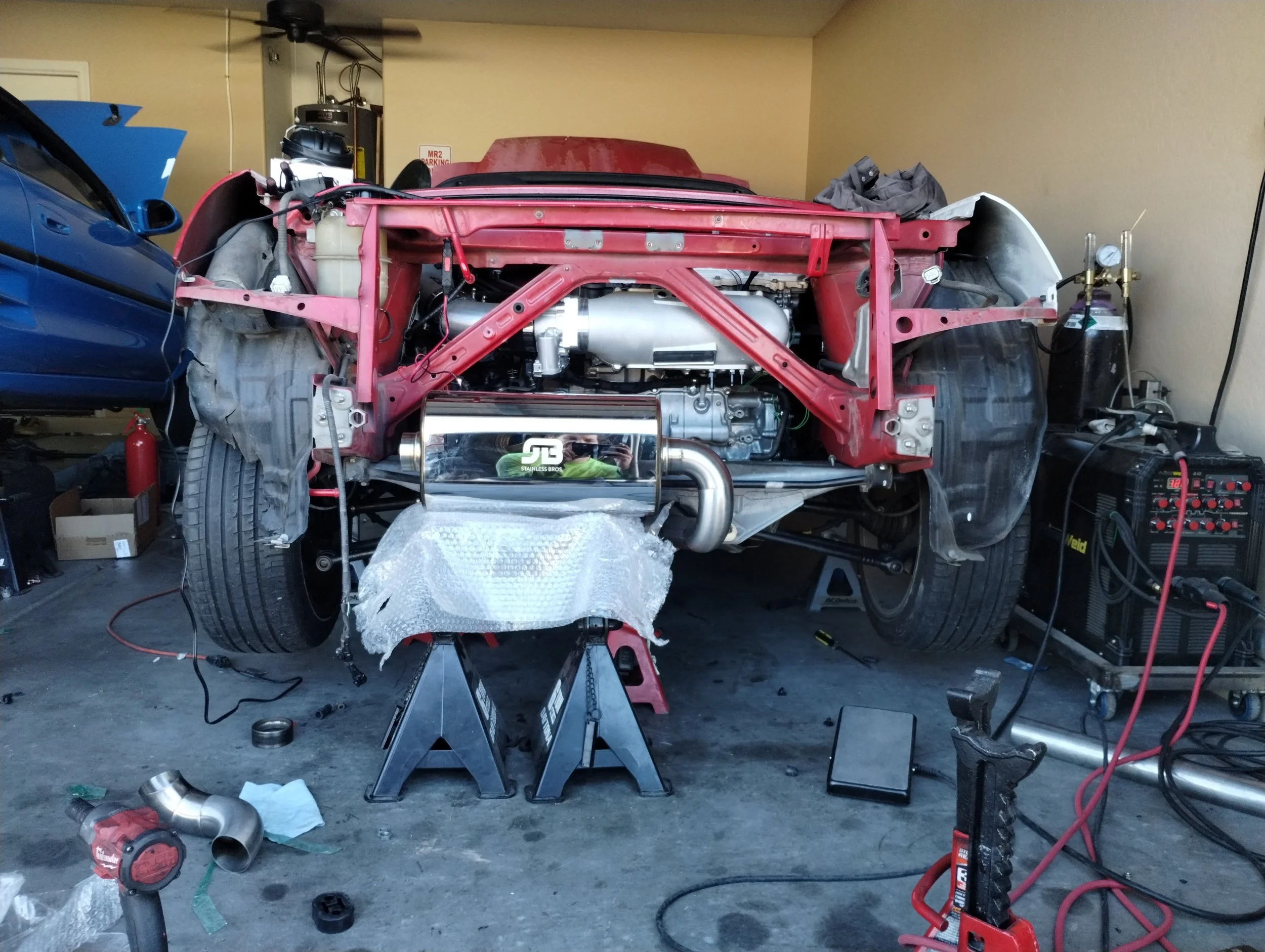
The second problem going under the subframe is having to go up a lot more in a really short distance, to keep the muffler positioned right. This also requires the muffler to be pushed further to the left, instead of being more centered. Alex Wilhelm put me onto these Stainless Bros mufflers, which is what he uses on 2GR X pipe setups. It’s a shame this all gets covered up. Maybe I’ll be like one of those Lamborghini dorks and drive around with no bumper just to show off my exhaust. Sounds like a V2 problem.
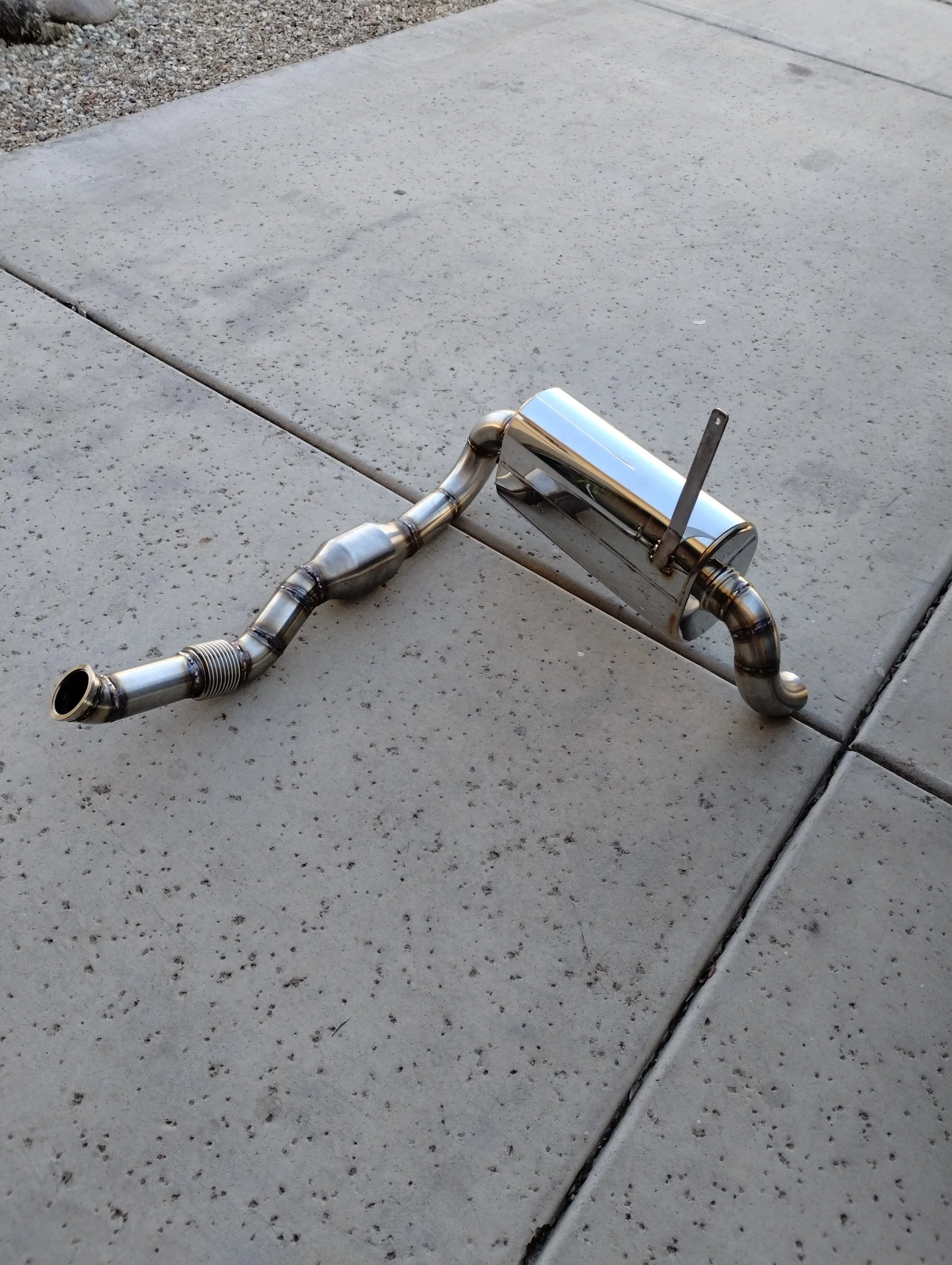
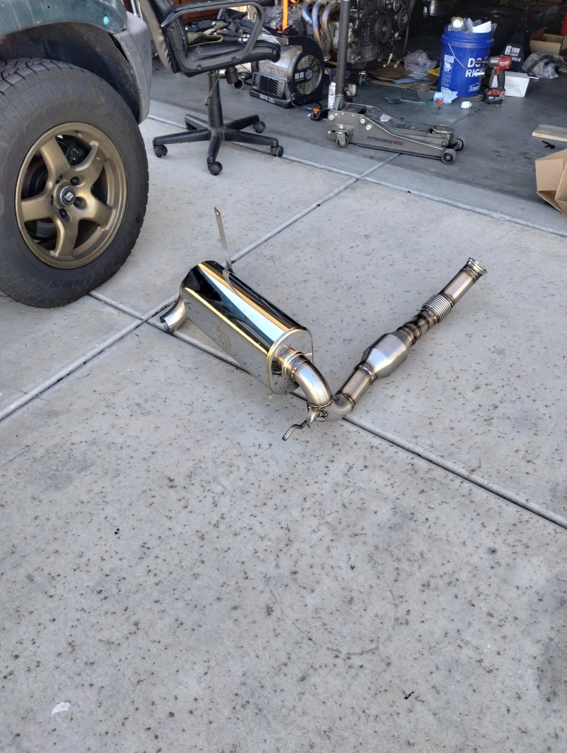
Don’t zoom in on some of those welds.
Next on the “I gotta finish this” list was the gas pedal. I wanted to use one of the newer hall effect pedal instead of the resistive element pedal typically used on 2AR Spyders. I’ve heard that Haltechs seem to work better with the hall effect pedals as well. I went back and forth on the design for a bit, but eventually I settled for good enough and came up with this:
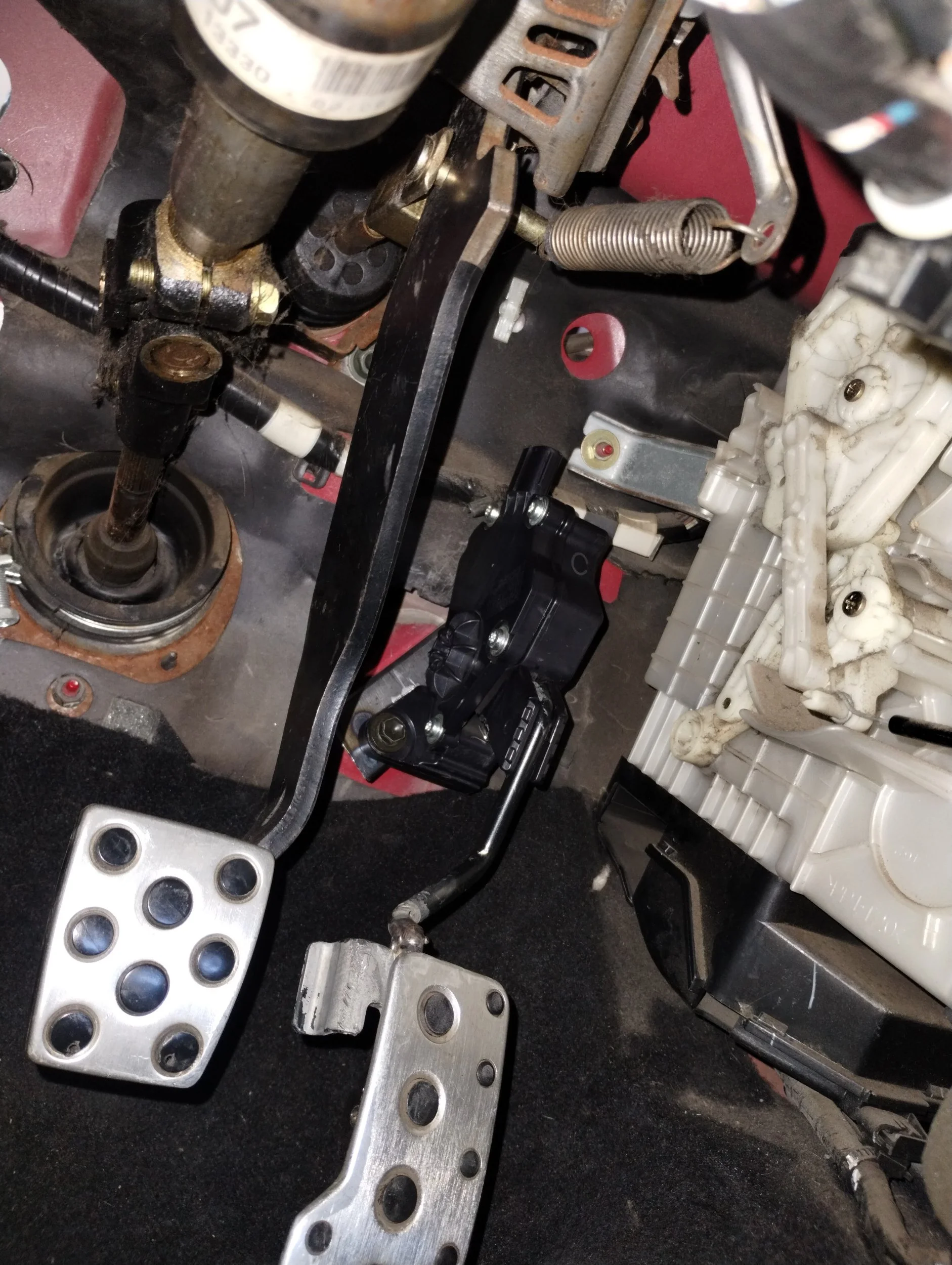
This is not my first rodeo, I had to do something similar with my RAV4 a few years ago. This time I used some 1” square tubing with a few holes drilled, angled appropriately to place the arc of the pedal parallel with the brake and clutch. I had to bend the pedal arm a fair bit, and accidentally snapped the pedal section off. I welded it back together as straight as I could and kept forming the shape. It’s a little lower than I’d like, and a tiny bit too far to the right, but it will work. The bracket is a little flimsy too, I think I need to add a small plate on top of this, and a third bolt hole on the firewall to stabilize it. Again, that’s something I did with my RAV4 a few years ago and that made a huge difference. This will work, but there’s room for improvement. That will come out in V2.
I made a short pedal-to-ECU harness, and this was about the time disaster struck. When trying to operate my throttle, I was getting nothing. No value on the pedal, no movement at the throttle body. I triple checked all the settings in my Haltech, everything checked out. After sleeping on it, and I realized the former was really easy to fix. I pinned my pedal harness according to Marc’s wiring guide, which used the older resistive element pedal, which has a different pinout. Same signals, I just had to move a few things around and was okay. The throttle body on the other hand, that was a bigger hassle. I was getting complete nonsense data. I double and triple checked the pinouts, and everything was correct. I bench tested the throttle body with a lab power supply, and still got nothing. The hall effect feedback signal was not changing with any throttle movement. I ended up taking it apart to check the circuits, make sure I had power going to the right pin.
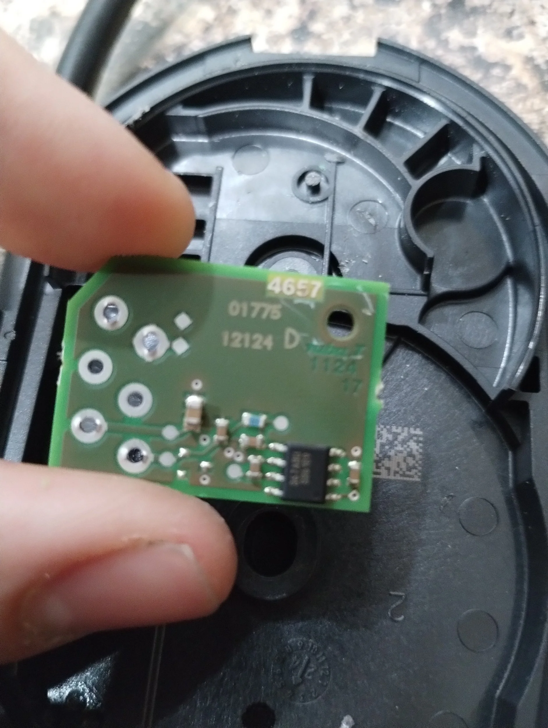
367ABU, huh?
I looked up the IC part number in an attempt to verify the pinout, and I notice it specifically calls out SENT protocol. I did a little more digging and found out this chip cannot supply an analog voltage feedback signal, SENT only. On the same token, Haltech cannot accept a SENT input for throttle position. Some of you may have caught this earlier, in my choice of a gen3 Coyote throttle body. I did a little more research, and everything pointed to gen1 throttle body sharing the same bolt pattern, connector, and pinout. I bought one of those, and it works. Phew. No additional work needed.
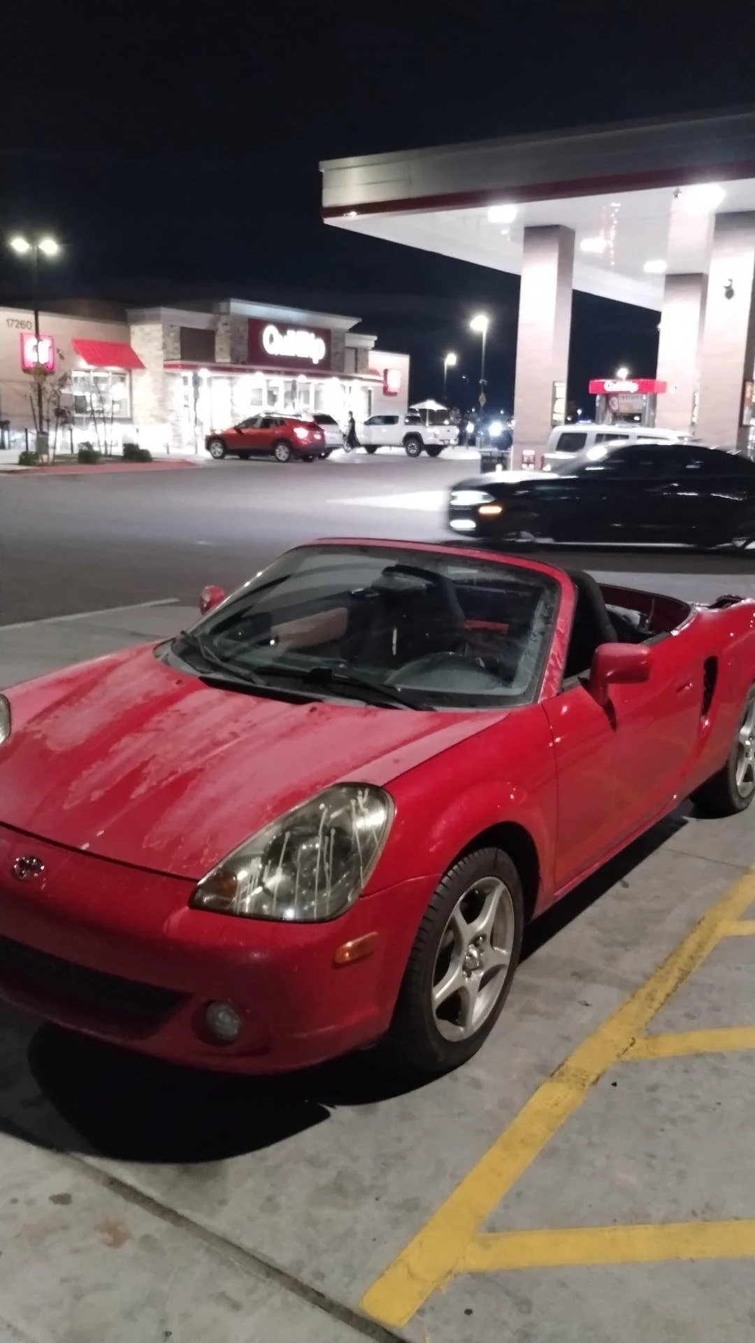
Well, that was everything, mechanically. About time for a first drive. First stop, the gas station. Not to get gas, but to fill my tires. My tire inflator bit the dust, and after sitting for a couple years I was down to 12-15psi in three tires. Nothing went wrong in my three mile drive, and this got a lot of attention, probably from all the missing body panels. It ran pretty rough, and it turned out I just had a few incorrect configurations in my ECU.
Non-exhaustive list of the problems I discovered:
Exhaust cam control direction set for retard, corrected to advance.
Exhaust cam 1 input: sensor type is hall effect with a pull up enabled; this is correct. A few problems here.
The Haltech’s internal pullup resistor only brings the voltage up slightly. This is a known issue. Mine had a low voltage of 0.15V, and a high of around 0.75V. Previously, the fix was to add an external pullup resistor. At some point, they fixed the firmware and allowed a “custom” sensor type with a the internal pull up enabled. I configured a custom sensor with a 0.5V activation voltage.
The above did not immediately work. A bit more research, and I figure out once you enable custom sensor, an arming voltage table appears. Some sensors change voltage depending on RPM. Hall effects really don’t, so I had to just make the whole table 0.5V. This worked.
Note: Typically, people wire these hall effect sensors to 8V, I wired mine to 5V, which is why my activation voltage is so low,
Both VVTi solenoids set for low side drivers, I wired these for high. Corrected to high side, and high active state.
After that last switch, my engine started idling smooth as butter, so I took it for another drive. This time, to the parts store to get brake lights. Feels a lot better. Still has a few hiccups, but good steps forward.
I still have to fix a handful of things in software, and I keep messing with the tune, but in reality this is completely driving. Stay tuned for future updates, as I get this tuned, and eventually get around to building the 2.7. I’ll leave you off with a little pull.