
FMW Spyder Body Controller Modifications
The Frankenstein Motorworks body controller provides integration for engine swapped MR2 Spyders. This is a junction box which simplifies connections, and communicates to the gauge cluster over the BEAN protocol for various functions. While this is incredibly thorough, there are a handful of shortcomings which can be easily remedied. For all modifications, ensure proper soldering terminations and support wires with kapton tape or similar, where applicable.
SMT Starter Ground
This modification is only applicable to factory sequential manual transmissions (SMT) vehicles. If your vehicle did not come with a sequential transmission, this mod is entirely unnecessary, however no function will be altered by this mod.
Problem:
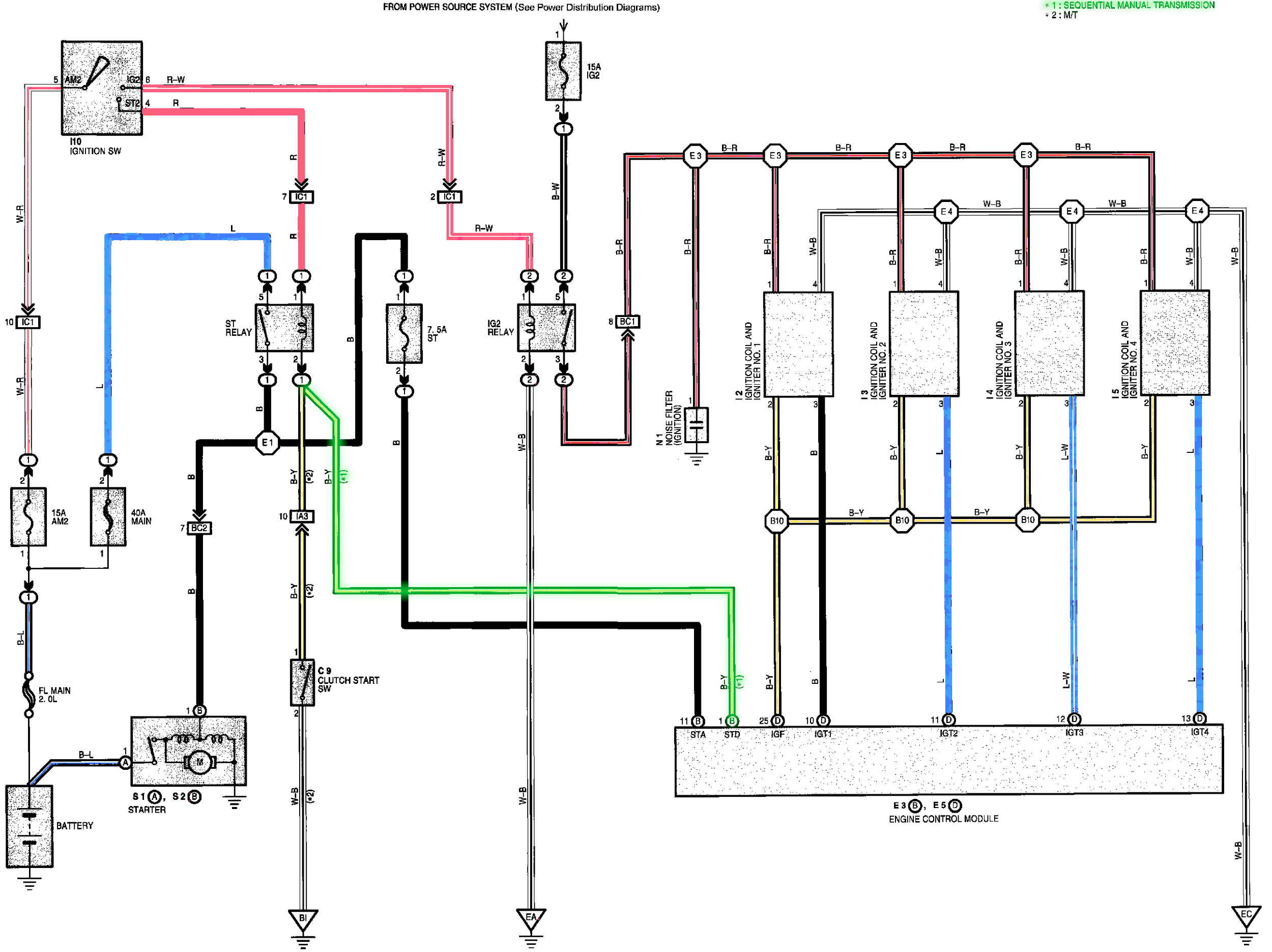
On SMT Spyders, the starter relay grounds through the ECU. This allows the ECU to check whether the SMT system is in neutral before enabling the starter.
Solution:
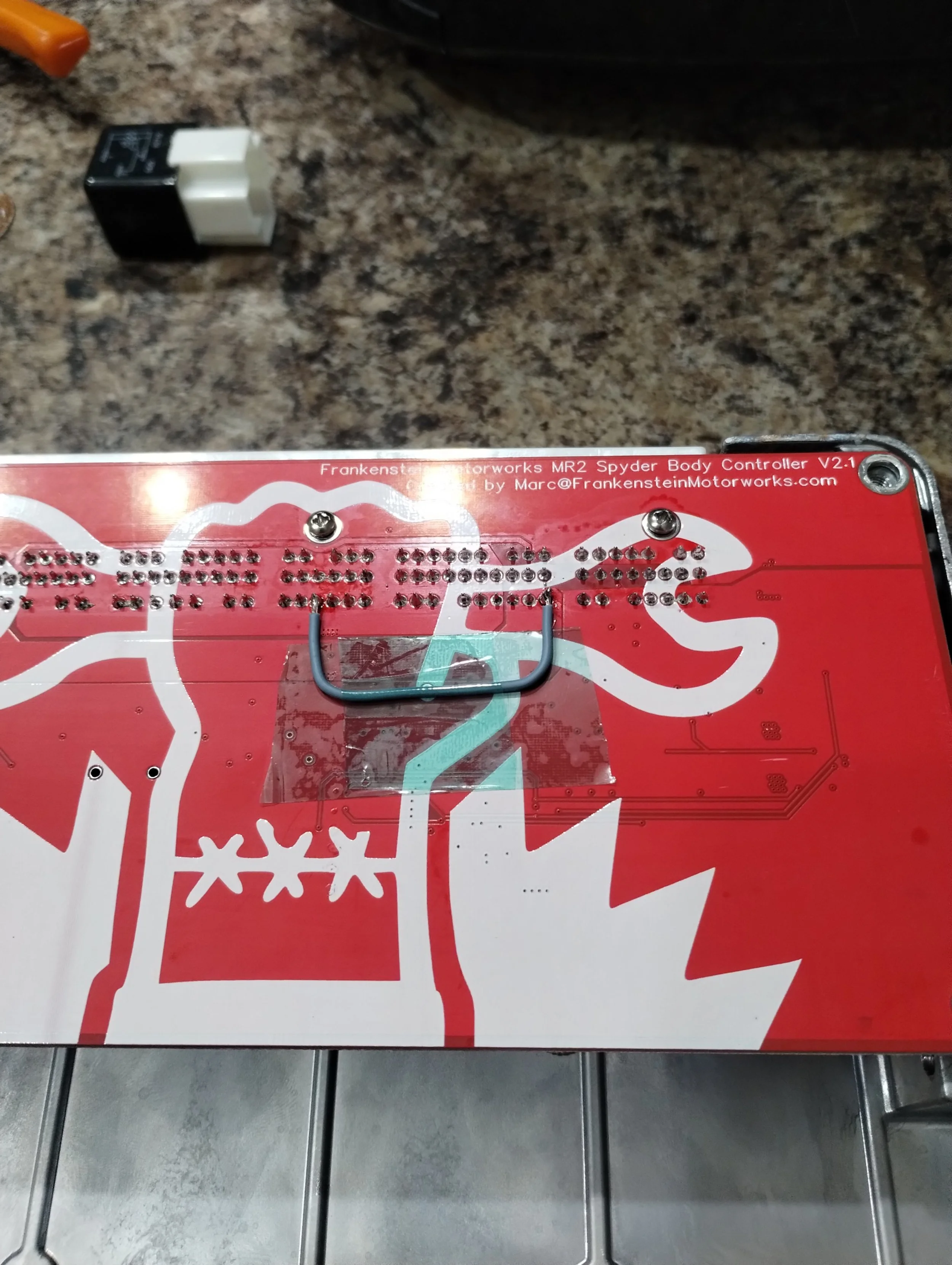
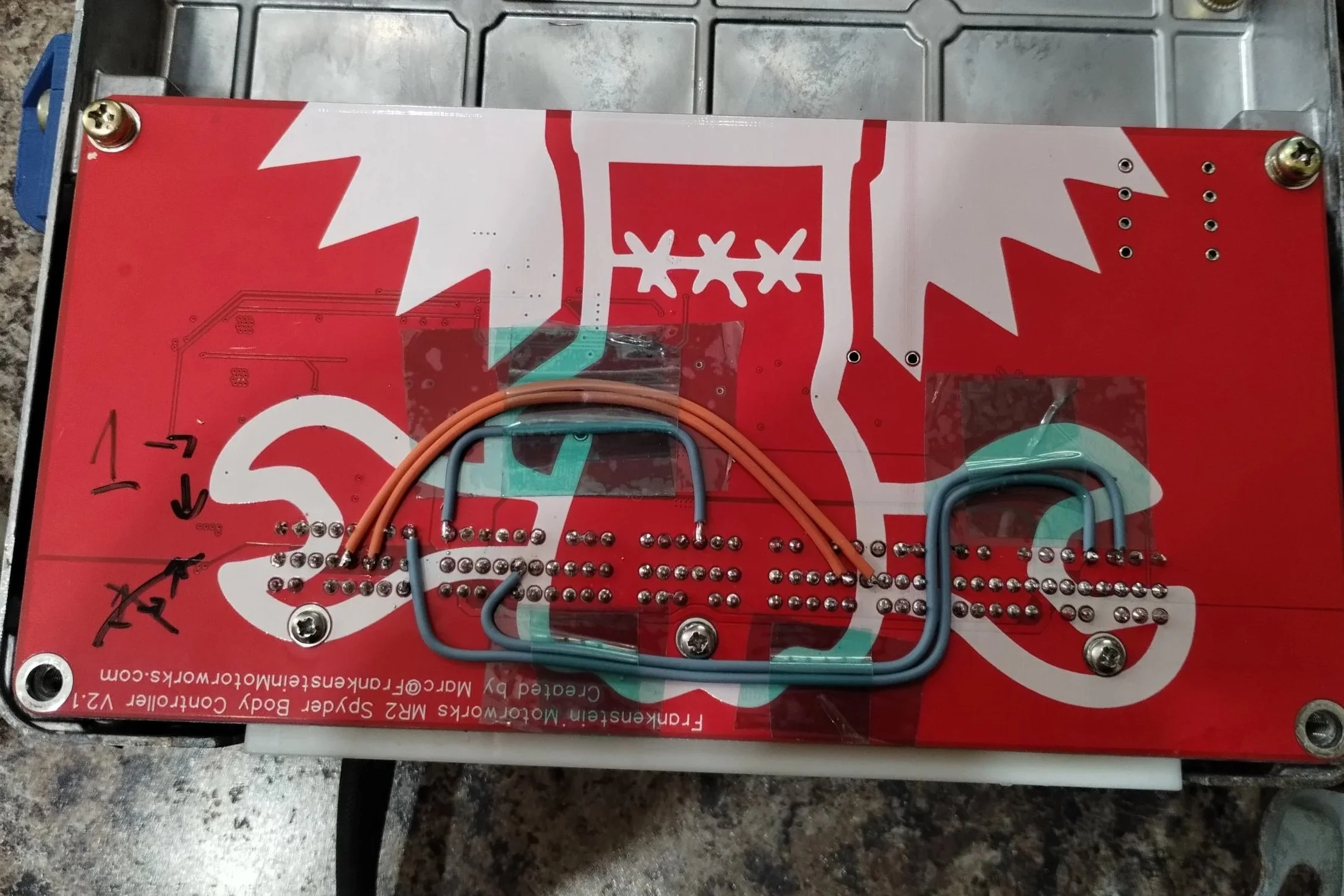
Solder a wire from E3-1 to 17P-4. This will correctly ground the starter relay to engine ground. See the lone blue wire in the image below.
Potential issues:
This skips any neutral safety switch. If you attempt to start your vehicle while the transmission is in gear, it will move unexpectedly. This may be undesirable, or even illegal in your region. Please check your local legislation and decide if this mod is correct for you. If a neutral safety switch is desired, a switch should be added following the OEM wiring diagram below.
Air Conditioner Clutch
Problem:
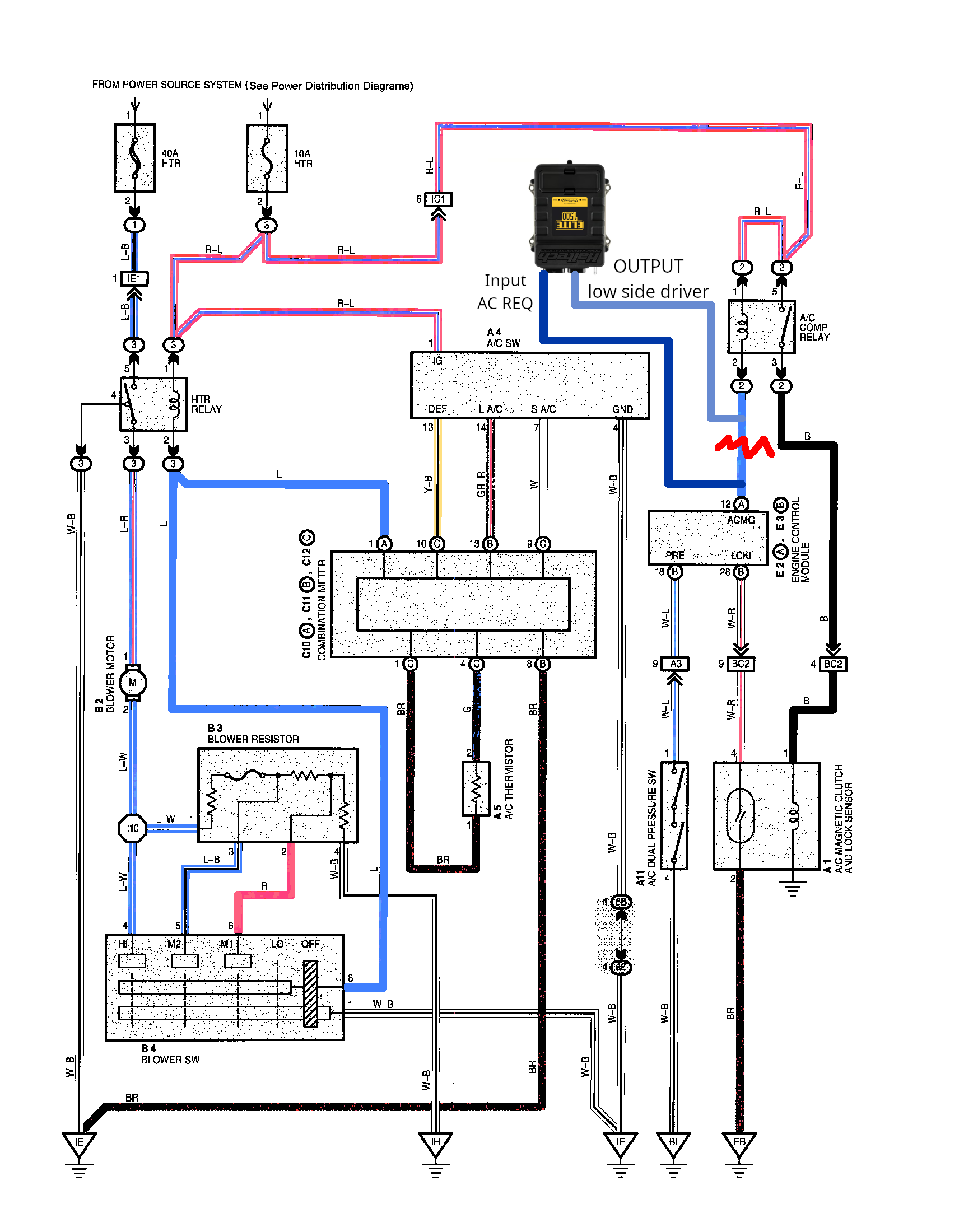
The body controller does not route the AC clutch command to the E4 or E5 integration connectors. This means that there is no way to enable an AC idle-up, for ECUs that support this. Additionally, some ECUs are capable of controlling the AC clutch, which would allow additional control such as high RPM lockouts, which would prevent overspeeding the compressor.
Solution:
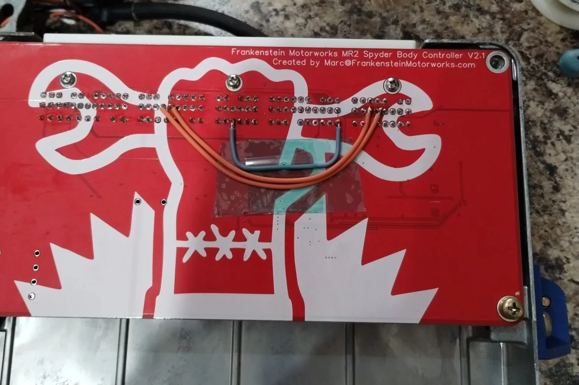
Solder a wire from E2-12 to E3-13, and from E2-13 to E3-12. After doing this, E3-13 becomes your AC request input to your ECU, and E3-12 becomes your AC clutch enable from your ECU. Wire these two pins to your ECU accordingly. See the two orange wires in the image below, as well as a sample diagram for what got modified.
Note 1: If you are not using your ECU to control the compressor, you may skip the E2-13 to E3-12 wire.
Note 2: If you are using the ECU to control the compressor, you must also move pin E2-12 on your body harness to E2-13.
Potential issues:
If using an ECU output, there is another point of failure. This could mean your AC stops working, which can be resolved by moving pin E2-13 back to E2-12, where it came from.
Cruise Control
Problem:
While the body controller passes the brake signal, inverted brake signal, and cruise control lever wiring, it does not have a passthrough for a clutch switch or cruise control light.
Solution:
Solder a wire from E2-7 to E5-6, and from E3-14 to E5-7. E5-6 becomes your clutch switch status, and E5-7 becomes your cruise light enable. See the two blue wires below.
Note 1: Only SMT Spyders came with a cruise light. I cannot verify whether the manual body harness has a wire in this position, but it is the factory position for SMT cars. Manual gauge clusters are also missing a transistor and LED for the cruise light.
Note 2: No USDM Spyders came with an upper clutch switch, E2-7 is the factory location for the SMT neutral switch, which is on the transmission. A new wire must be ran from your clutch pedal to this pin location. If you have a non-US market manual car with cruise control, with a 1ZZ, please contact me, I’m interested to see how this is wired up.
Note 3: The cruise LED must be a low side driver, with a low active state. If this is not how your ECU outputs a cruise LED, you can use relay logic to invert this.
2026/03/19: I plan to add any future modifications to this page in the future. Other things on my list include a chassis-side flex fuel sensor, and potentially a gear display. Check back in the future to see any more details.